Wave recorder fixing device with protecting function

A technology of fixing device and protection function, which is applied in the field of oscilloscope, can solve the problems of inconvenient operation, inability to change the direction and inclination angle during operation, and inconvenient operation for the operator, so as to achieve convenient operation, convenient installation and disassembly, and faster The effect of heat dissipation

Active Publication Date: 2018-12-21
江苏大财纳农牧科技有限公司
View PDF5 Cites 8 Cited by
  • Summary
  • Abstract
  • Description
  • Claims
  • Application Information

AI Technical Summary

Problems solved by technology

[0004] The object of the present invention is to provide a oscilloscope fixing device with a protective function, to solve the problem that the oscilloscope proposed in the above background technology is placed on the ground, and the staff needs to squat up many times, which is very inconvenient to operate, while the existing Most of the wave recorder fixing devices fix the wave recorder directly on the fixed frame, so the direction and tilt angle cannot be changed during operation, which is inconvenient for the operator to operate

Method used


Image

  • Wave recorder fixing device with protecting function
  • Wave recorder fixing device with protecting function
  • Wave recorder fixing device with protecting function

Examples


Embodiment 1

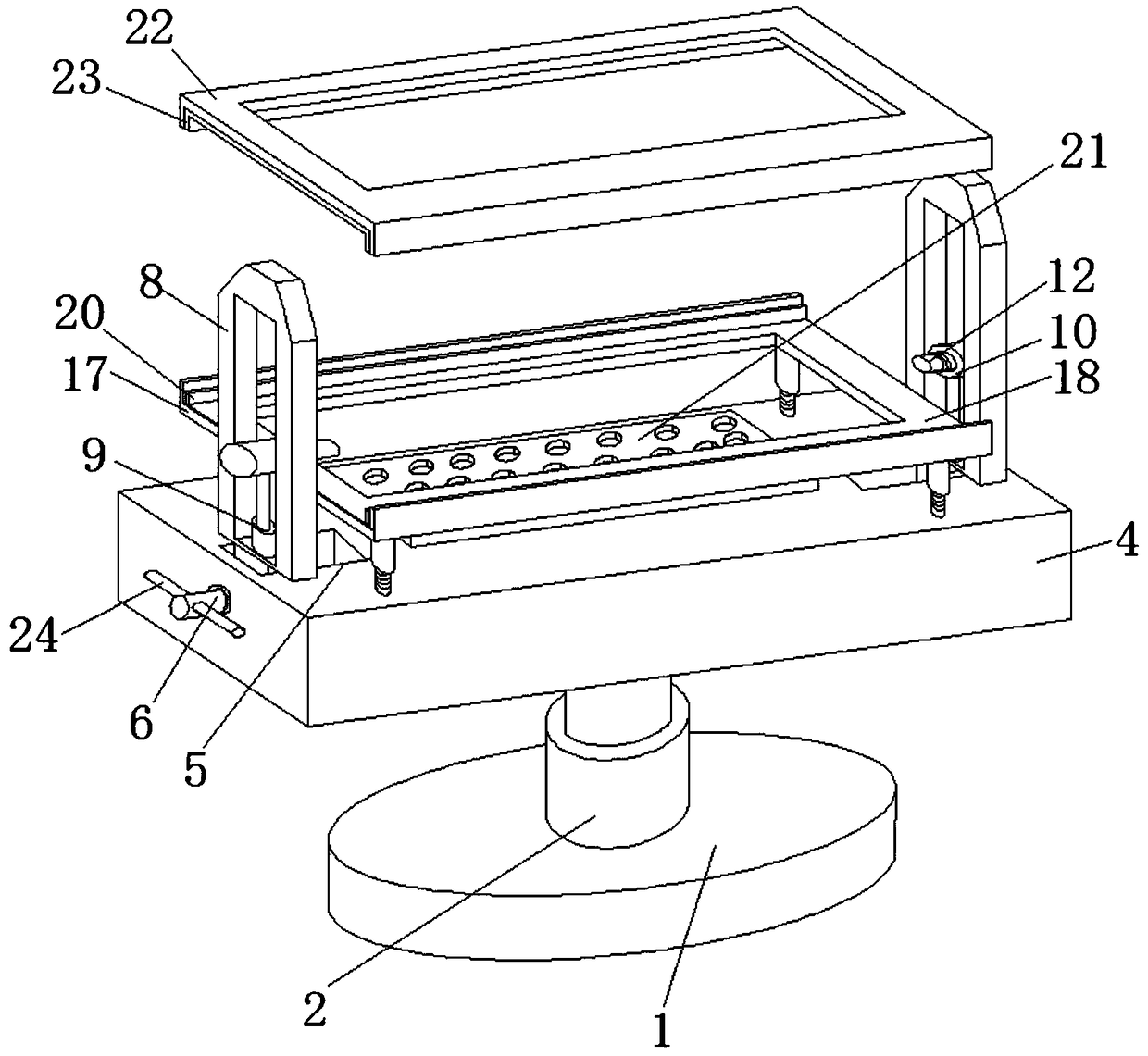
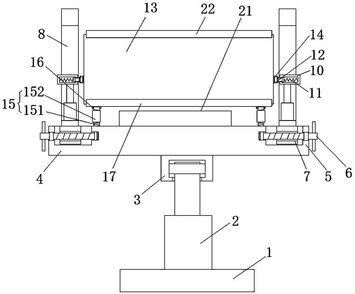
[0023] see Figure 1-4 , this embodiment provides a oscilloscope fixing device with a protective function, including a base plate 1 and an oscilloscope body 13, the top of the base plate 1 is fixedly connected with an air pressure rod 2, and the top of the air pressure rod 2 is rotatably connected with a rotating seat 3 , the top of the rotating base 3 is fixedly installed with a support plate 4, the top of the support plate 4 is provided with a mounting groove 5, the inner wall of the mounting groove 5 is rotatably connected with a screw rod 6, and the surface of the screw rod 6 is threadedly connected with a sliding block 7, the sliding block The top of 7 is fixedly connected with frame 8, and the bottom of the inner wall of frame 8 is fixedly connected with electric push rod 9, and the top of electric push rod 9 is fixedly connected with installation sleeve 10, and the inner wall of installation sleeve 10 is provided with positioning spring 11, and positioning spring One si...

Embodiment 2

[0026] see Figure 1-4 , on the basis of embodiment 1, a further improvement has been made: the inner wall of the rotating seat 3 is provided with a bearing, and the air pressure rod 2 is socketed with the bearing. Through the rotation of the bearing, the support plate 4 can be supported under the condition that the position of the air pressure rod 2 remains unchanged. The position of the wave recorder body 13 is changed, so as to change the position of the wave recorder body 13. One side of the screw rod 6 is fixedly provided with a handle 24. When the wave recorder body 13 is disassembled and installed, the screw rod 6 and the installation groove 5 joints are provided with bearings, the screw mandrel 6 is socketed with the inner ring of the bearing, the position of the frame 8 can be changed more conveniently through the handle 24, and the bearings at this place can make the rotation of the screw mandrel 6 smoother. It facilitates disassembly and installation operations.

...


PUM


Abstract

The invention discloses a wave recorder fixing device with a protecting function. The device comprises a base plate and a wave recorder body; the top of the base plate is fixedly connected with an airpressure rod; the top of the air pressure rod is rotationally connected with a rotating base; a support plate is fixedly mounted at the top of the rotating base; a mounting groove is formed in the top of the support plate; a lead screw is rotationally connected to the inner wall of the mounting groove; a slide block is in threaded connection to the surface of the lead screw; a frame is fixedly connected to the top of the slide block; the bottom of the inner wall of the frame is fixedly connected with an electric push rod; the top of the electric push rod is fixedly connected with a mounting sleeve; a positioning spring is arranged on the inner wall of the mounting sleeve; and one side of the positioning spring is fixedly connected with a positioning column. The device solves the problemsof incapability of changing the operation direction and the inclined angle and inconvenience for operators to operate due to direct fixation of wave recorders on fixed frames in most traditional waverecorder fixing devices.

Description

technical field [0001] The invention relates to the technical field of oscilloscopes, in particular to a oscilloscope fixing device with a protection function. Background technique [0002] The waveform recorder, also known as the wave recorder, is a transient signal recording instrument developed for power system applications. The internal software of the instrument is preset with a test template for generator debugging, so that users can easily complete the short-circuit characteristics of the generator through the recorder. Test, no-load characteristic test, excitation system disturbance test, excitation system 10% step test, de-excitation constant measurement, self-calibration synchronization device calibration, unit load shedding record and other tests. [0003] When the existing oscilloscope is used, due to the large volume of the oscilloscope, most of them are placed on the ground or fixed on a fixed frame for operation, but the staff who place it on the ground need t...

Claims


Application Information

Patent Timeline
Patent Type & Authority Applications(China)
IPC IPC(8): F16M11/28F16M11/10F16M11/04H05K7/20
CPCF16M11/041F16M11/10F16M11/28H05K7/20
Inventor 朱洋乐丹丹
Owner 江苏大财纳农牧科技有限公司
Why Eureka
Try Eureka