
LED lamp with high light effect

A LED lamp with high luminous efficiency technology, applied in the field of lighting, can solve the problems of uneven luminescence and low luminous efficiency, and achieve the effects of uniform luminescence, high luminous efficiency and less drift of color coordinates

Inactive Publication Date: 2018-12-21
程立章
View PDF5 Cites 0 Cited by
  • Summary
  • Abstract
  • Description
  • Claims
  • Application Information

AI Technical Summary

Problems solved by technology

[0004] The problem to be solved by the present invention is to provide a LED lamp with high luminous efficiency to overcome the defects of uneven luminescence and low luminous efficiency in the prior art

Method used


Image

  • LED lamp with high light effect

Examples


Embodiment Construction

[0012] The specific implementation manners of the present invention will be further described in detail below in conjunction with the accompanying drawings and embodiments. The following examples are used to illustrate the present invention, but are not intended to limit the scope of the present invention.

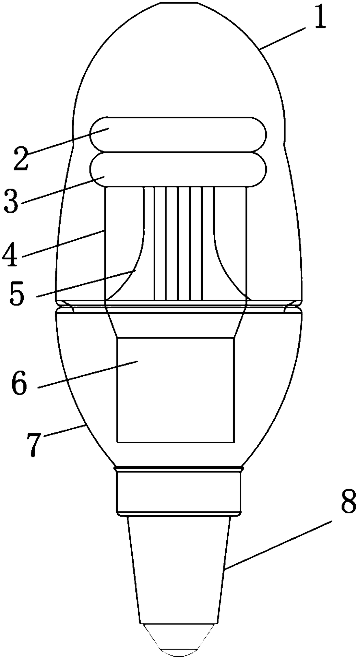
[0013] Such as figure 1 As shown, a high-efficiency LED lamp of the present invention includes a translucent lampshade 1, a first LED light strip 2, a second LED light strip 3, a wire 4, a heat-dissipating aluminum substrate 5, a power supply 6, and a lamp holder 7 and mounting base 8; the upper end of the lamp base 7 is screwed and fixed with the internal and external threads of the translucent lampshade 1, and the lower end is screwed and fixed with the internal and external threads of the mounting base 8; the power supply 6 is detachably arranged on the The upper interior of the lamp holder 7; the heat dissipation aluminum substrate 5 is arranged inside the translucent...


PUM


Abstract

The invention provides an LED lamp with a high light effect. The LED lamp comprises a semi-transparent lampshade, a first LED luminescence lamp strip, a second LED luminescence lamp strip, a wire, a heat dissipation aluminum substrate, a power supply, a lamp holder and a mounting base; the upper end of the lamp holder is fixed with the semi-transparent lampshade in an internal and external threadscrewing mode, and the lower end of the lamp holder is fixed with the mounting base in an internal and external thread screwing mode; the power supply is detachably arranged in the lamp holder; and the heat dissipation aluminum substrate is arranged in the semi-transparent lampshade and installed at the power supply end. The LED lamp has the advantages that the structure is simple, luminescence ismore uniform, and the light effect is higher; and in long-term use, the lumen maintenance is better, and the color coordinate drift is less.

Description

technical field [0001] The invention relates to the technical field of lighting, in particular to an LED lamp with high light efficiency. Background technique [0002] LED (is a solid-state semiconductor device that can convert electrical energy into visible light. It can directly convert electricity into light. The heart of the LED is a semiconductor wafer. One end of the wafer is attached to a bracket, one end is the negative pole, and the other end Connect the positive pole of the power supply so that the entire chip is encapsulated by epoxy resin. The semiconductor chip is composed of two parts, one part is a P-type semiconductor, in which holes dominate, and the other end is an N-type semiconductor, where mainly electrons But when the two semiconductors are connected, a P-N junction is formed between them. When the current acts on the wafer through the wire, the electrons will be pushed to the P region, where the electrons recombine with the holes, Then it will emit en...

Claims


Application Information

Patent Timeline
Patent Type & Authority Applications(China)
IPC IPC(8): F21S9/02F21V3/12F21V19/00F21Y115/10
CPCF21S9/02F21V3/12F21V19/001F21Y2115/10
Inventor 程立章
Owner 程立章
Learn More