
Module quality detecting device

A detection device and quality technology, which is applied to measurement devices, mechanical measurement devices, and mechanical devices, etc., can solve the problems that detection pins can only move up and down and cannot be adjusted at multiple angles, so as to improve representativeness and reduce use limitations. , the effect of improving adaptability

Inactive Publication Date: 2018-12-21
YANCHENG HUAXU OPTOELECTRONICS TECH CO LTD
View PDF0 Cites 2 Cited by
  • Summary
  • Abstract
  • Description
  • Claims
  • Application Information

AI Technical Summary

Problems solved by technology

[0002] As we all know, the module quality inspection device is an auxiliary device used for quality inspection in the process of module production and assembly, so as to better produce high-quality modules. It has been widely used in the field of quality inspection. Use; the existing module quality inspection device includes a detection box, two groups of left outriggers, two groups of right outriggers, an electric cylinder, a detection pin and a detection table, the inside of the detection box is provided with a detection cavity, and the front end of the detection box is provided with Operation port, the operation port communicates with the inside of the detection chamber, four sets of struts are arranged at the bottom of the detection table, and the bottom ends of the four sets of struts are connected with the left front side, left rear side, right front side and right rear side of the inner wall of the bottom end of the detection chamber Connection, the top of the electric cylinder is connected to the middle of the top inner wall of the detection chamber, and the top of the detection pin is fixedly installed on the bottom output end of the electric cylinder, and the top of the console is provided with four sets of suction cups, and the bottom of the four sets of suction cups are connected to the detection table The left front side, left rear side, right front side and right rear side of the top are connected, the tops of two groups of left outriggers are respectively connected with the left front side and left rear side of the outer wall of the bottom end of the detection box, and the tops of two groups of right outriggers are respectively connected with the bottom of the detection box The right front side and the right rear side of the inner wall of the terminal are connected; when the existing module quality inspection device is used, first place the module horizontally on the inspection table, and use four sets of suction cups to hold it, and then open the electric cylinder, the electric cylinder Move downwards to drive the detection pin to move downward until the probe at the bottom of the detection pin touches the top of the module for detection; it is found in the use of the existing module quality detection device that the detection pin can only move up and down. Multi-angle adjustment is not possible. When multi-point detection of the module is required, the module needs to be removed from the detection table, replaced, and then the electric cylinder is opened to drive the detection pin for detection. The operation is cumbersome and the adaptability is poor; at the same time The module can only be tested at the same temperature, the detection data is not comprehensive, the representativeness is poor, and the reliability is low; and because the stroke of the electric cylinder is limited, the height of the detection table is limited, sometimes it is necessary to test thin modules , the probe of the detection pin often cannot touch the module, resulting in the inability to perform detection, and the use limitations are relatively high

Method used


Image

  • Module quality detecting device
  • Module quality detecting device
  • Module quality detecting device

Examples


Embodiment Construction

[0019] The specific implementation manners of the present invention will be further described in detail below in conjunction with the accompanying drawings and embodiments. The following examples are used to illustrate the present invention, but are not intended to limit the scope of the present invention.

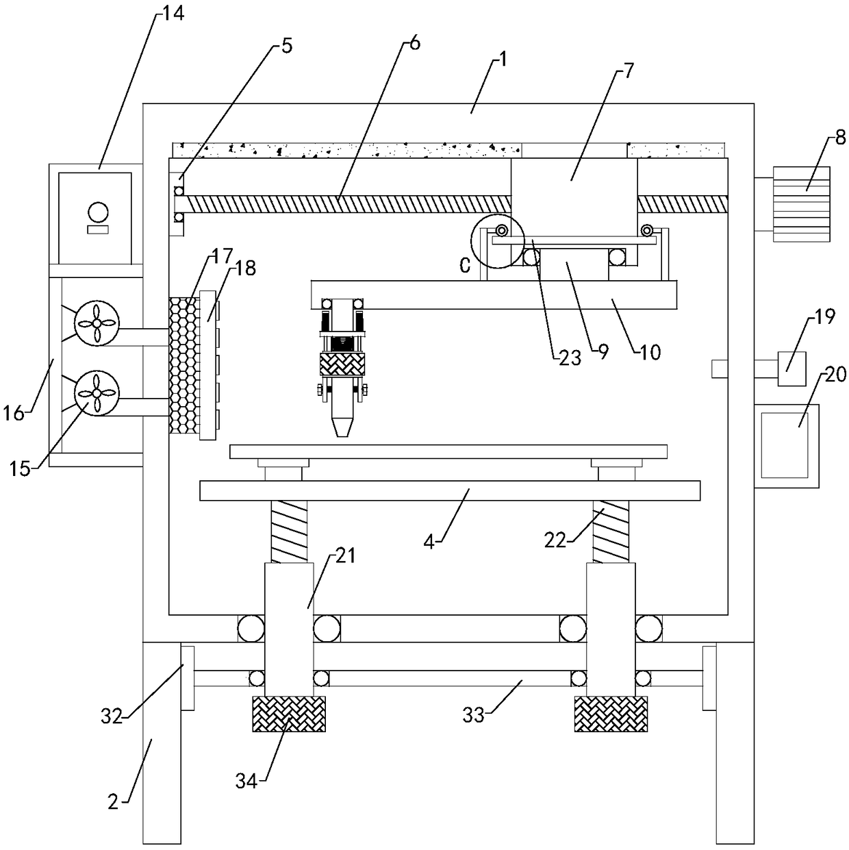
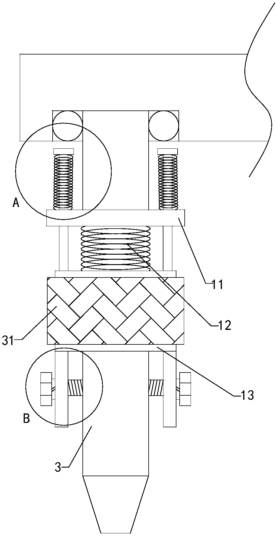
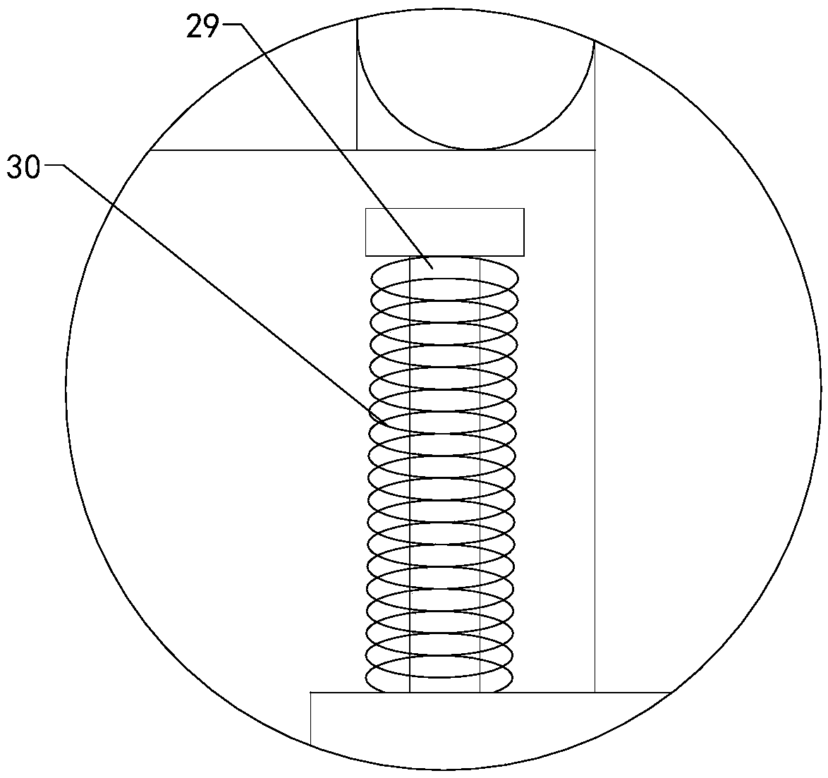
[0020] like Figure 1 to Figure 5 As shown, a module quality detection device of the present invention includes a detection box 1, two sets of left outriggers 2, two sets of right outriggers, a detection pin 3 and a detection platform 4. A detection cavity is arranged inside the detection box, and the detection The front end of the box is provided with an operation port, and the operation port communicates with the inside of the detection chamber. There are four sets of suction cups on the top of the operation table. Connection, the tops of two sets of left outriggers are respectively connected with the left front side and left rear side of the outer wall of the bottom en...


PUM


Abstract

The invention relates to the technical field of module quality accessory devices, in particular to a module quality detecting device, wherein a detecting pin can be adjusted at multiple angles, can perform multi-point detection on the module, has simple operation and improves adaptability; at the same time, the module can be detected at different temperatures, the detected data is comprehensive, the representativeness is improved, and the reliability of use is improved; and the height of a detecting table can be adjusted according to the modules of different thicknesses, thereby preventing theprobe of the detection pin from not touching the module and reducing the use imitation. The module quality detecting device includes a detection box, two sets of left legs, two sets of right legs, adetection pin and a detection table, wherein a detection chamber is provided in the detection box. The module quality detecting device includes a fixed plate, an adjusting screw, an adjusting block, an adjusting motor, a first rotating shaft, a second rotating shaft, a rotating arm, a mounting plate, a connecting spring and a mounting head, further includes a thermostat, two sets of fans, an upperbaffle, a lower baffle, a left baffle, a heating box, an exhaust hood, a temperature sensor and a display, and also includes four sets of threaded tubes and four sets of threaded rods.

Description

technical field [0001] The invention relates to the technical field of module quality attachment devices, in particular to a module quality detection device. Background technique [0002] As we all know, the module quality inspection device is an auxiliary device used for quality inspection in the process of module production and assembly, so as to better produce high-quality modules. It has been widely used in the field of quality inspection. Use; the existing module quality inspection device includes a detection box, two groups of left outriggers, two groups of right outriggers, an electric cylinder, a detection pin and a detection table, the inside of the detection box is provided with a detection cavity, and the front end of the detection box is provided with Operation port, the operation port communicates with the inside of the detection chamber, four sets of struts are arranged at the bottom of the detection table, and the bottom ends of the four sets of struts are con...

Claims


Application Information

Patent Timeline
Patent Type & Authority Applications(China)
IPC IPC(8): G01B5/00
CPCG01B5/00G01B5/0002
Inventor 凡永亮高金生李会斌
Owner YANCHENG HUAXU OPTOELECTRONICS TECH CO LTD
Learn More