
Airtight detection device

A technology for air tightness detection and equipment, which is used in liquid/vacuum degree measurement for liquid tightness, electromagnetic measurement device, and electromagnetic/magnetic thickness measurement. , to achieve the effect of reducing workpiece loss, broad market prospects, and improving detection efficiency

Pending Publication Date: 2018-12-21
SUZHOU INST OF INDAL TECH
View PDF6 Cites 6 Cited by
  • Summary
  • Abstract
  • Description
  • Claims
  • Application Information

AI Technical Summary

Problems solved by technology

[0002] Existing airtight testing equipment needs to go through multiple processes to achieve multiple tests to determine the pass rate of the product. In the prior art, the operation of multiple processes is carried out in traditional industries. Many operators use manual testing. In this process, it is necessary to complete multiple inspection procedures through manual cooperation. However, in the process of carrying out multiple procedures, firstly, due to the inconsistent operation level of each person, it is easy to cause inconsistency in detection and detection. Secondly, due to the need in the inspection Manual handling of the workpiece, or manual operation can easily damage the precision parts on the workpiece
This is time-consuming and labor-intensive, and the work efficiency is low; at the same time, in the process of manual operation, it is easy to cause errors in product testing data, and it is easy to cause product damage. Operators are prone to operating errors, resulting in increased product failure rates and increased production costs.

Method used


Image

  • Airtight detection device
  • Airtight detection device
  • Airtight detection device

Examples


Embodiment Construction

[0042] In order to make the technical means, creative features, goals and effects achieved by the present invention easy to understand, the present invention will be further described below in conjunction with specific embodiments.

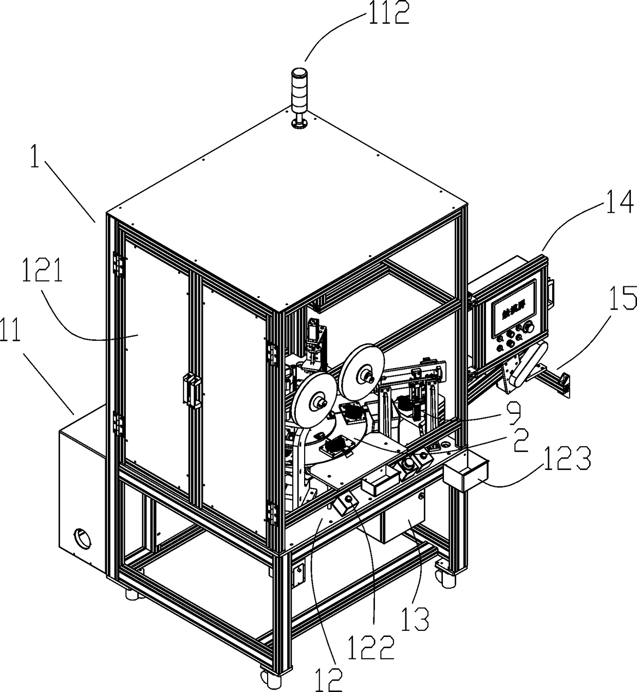
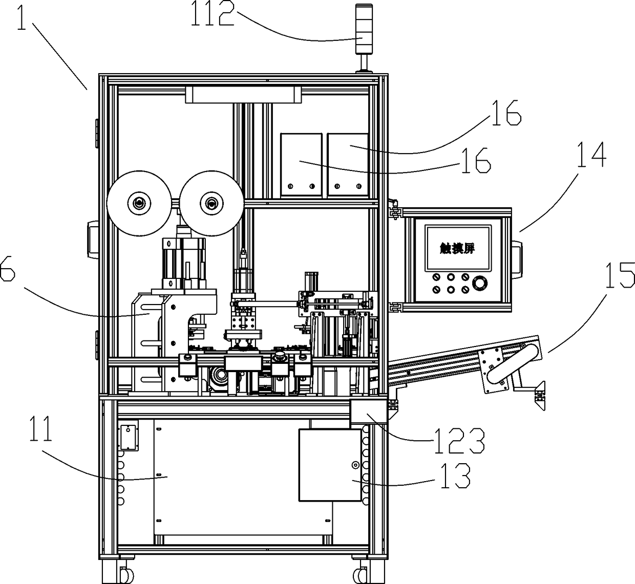
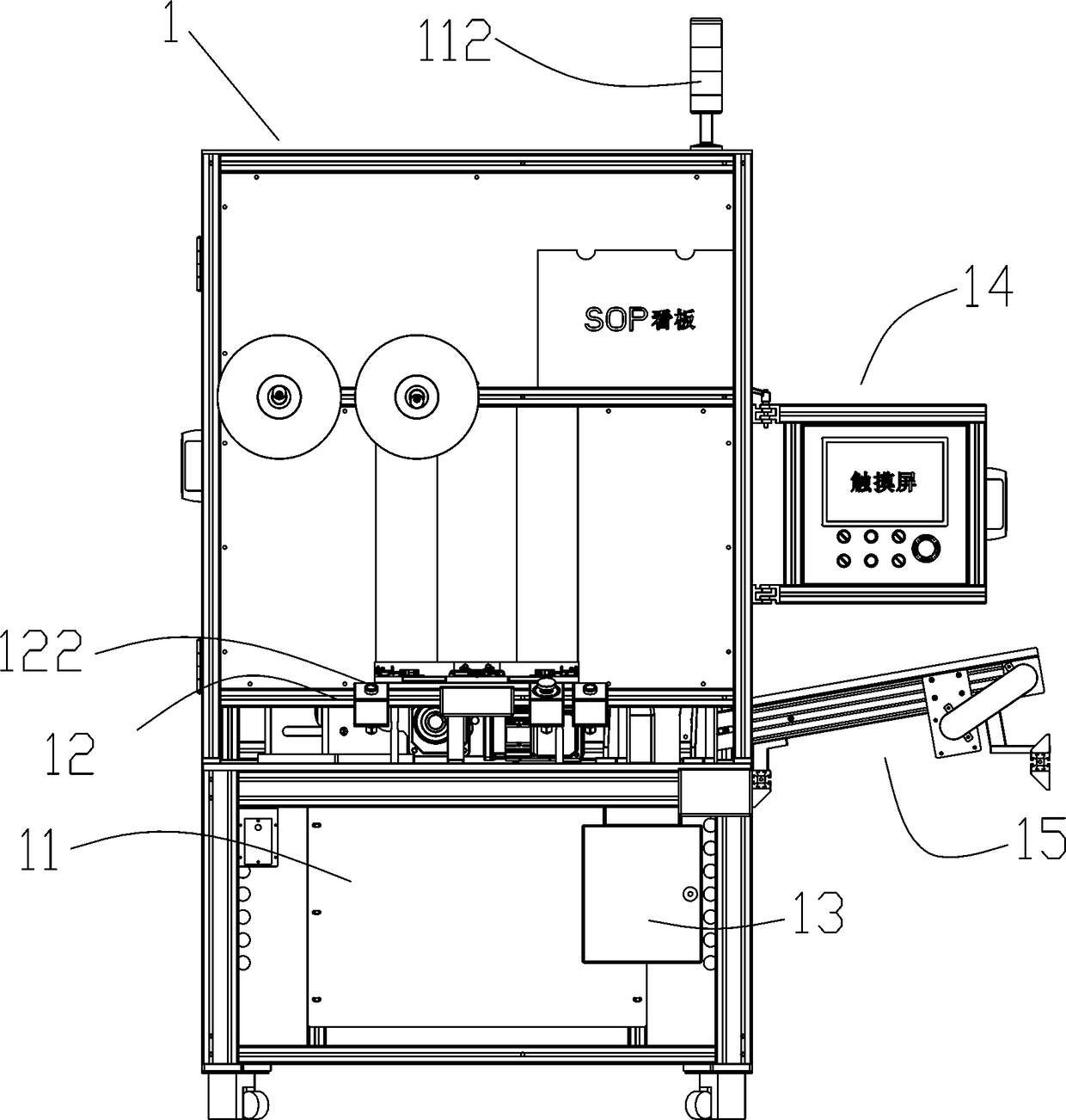
[0043] Such as Figure 1~Figure 24 As shown, it is a kind of airtight testing equipment of the present invention. The airtight testing equipment is provided with an integral body frame 1, and an airtight testing area, an operating area 2, and unqualified workpieces are sequentially arranged inside the overall body frame 1 from top to bottom. Placement area, the operation area 2 is provided with a working platform 3, the working platform 3 is provided with a turntable mechanism 4, the airtight detection area is provided with 2 sets of airtight detectors 16, and the unqualified workpiece placement area below the working platform 3 is provided with an alarm. The waste box 13 and the turntable mechanism 4 are electrically connected with the control box ...


PUM


Abstract

The invention discloses an airtight detection device, comprising an integral body frame. The integral body frame is provided with an airtight detection zone, an operation zone and an unqualified workpiece placement zone from top to bottom, wherein the operation zone is provided with a working platform; the working platform is provided with a rotary disc mechanism; the airtight detection zone is provided with an airtight detector; the unqualified workpiece placement zone is provided with a waste material box; the rotary disc mechanism is electrically connected with a control box; the working platform is provided with a feeding mounting device, an elastic sheet riveting device, an integral airtight detection device, a thin film airtight detection device, an elastic sheet height detection device and a mechanical arm material distributing device which are electrically connected with the control box in sequence along a material conveying direction; one side of the working platform is connected with a material conveying channel; and the outer portion of the integral body frame is provided with a touch screen and an SOP watch plate. According to the airtight detection device, mechanical automation can be achieved, detection efficiency can be improved, workpiece loss can be reduced and airtight detection accuracy can be improved.

Description

technical field [0001] The invention relates to the technical field of airtight detection, in particular to an airtight detection device. Background technique [0002] Existing airtight testing equipment needs to realize multiple inspections through multiple processes to determine the pass rate of the product. In the prior art, the operation of multiple processes is carried out in traditional industries. Many operators pass manual inspections. In this process, it is necessary to complete multiple inspection procedures through manual cooperation. However, in the project of carrying out multiple procedures, firstly, due to the inconsistent operation level of each person, it is easy to cause inconsistency in detection and detection. Secondly, due to the need for The precision parts on the workpiece are easy to be damaged by manual handling of the workpiece or manual operation. This is time-consuming and labor-intensive, and the work efficiency is low; at the same time, in the ...

Claims


Application Information

Patent Timeline
Patent Type & Authority Applications(China)
IPC IPC(8): G01M3/26G01B7/06
CPCG01B7/06G01M3/26
Inventor 黄华栋李长春徐振宇方彪庄南洋
Owner SUZHOU INST OF INDAL TECH
Learn More