Connector PIN height measuring device and using method thereof

A height measurement device and connector technology, which is applied in the direction of measurement devices, optical devices, instruments, etc., can solve the problems of increased inspection costs and expensive laser scanners, and achieve reduced inspection costs, strong copy compatibility, and the number of components little effect

Pending Publication Date: 2020-07-17
苏州凌创科技发展有限公司
View PDF2 Cites 1 Cited by
  • Summary
  • Abstract
  • Description
  • Claims
  • Application Information

AI Technical Summary

Problems solved by technology

Although this type of equipment can obtain the height of the PIN pin on the entire product surface, it needs to use a laser scanner to obtain the distance between the product surface and the detection instrument. However, the laser scanner is relatively expensive, which increases the detection cost

Method used


Image

  • Connector PIN height measuring device and using method thereof
  • Connector PIN height measuring device and using method thereof
  • Connector PIN height measuring device and using method thereof

Examples


Embodiment 1

[0046] This embodiment mainly introduces the basic composition and connection relationship of a connector PIN pin height measuring device of the present invention.

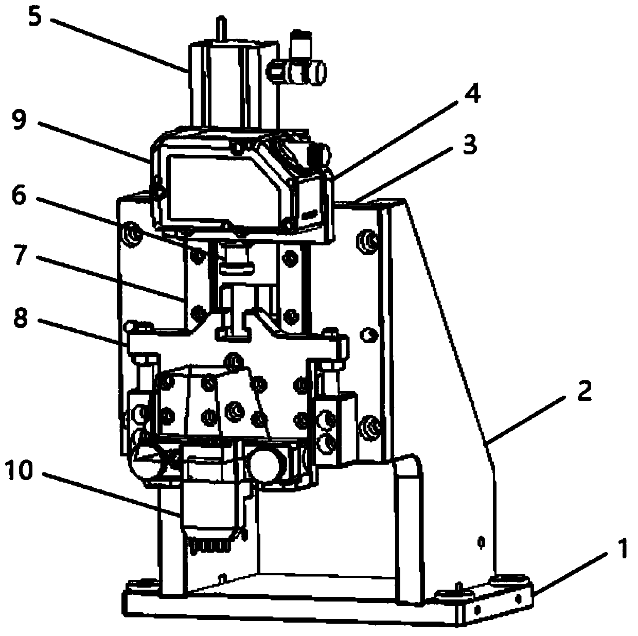
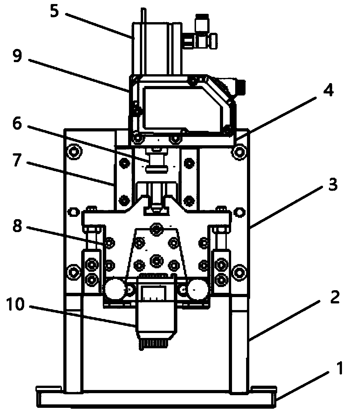
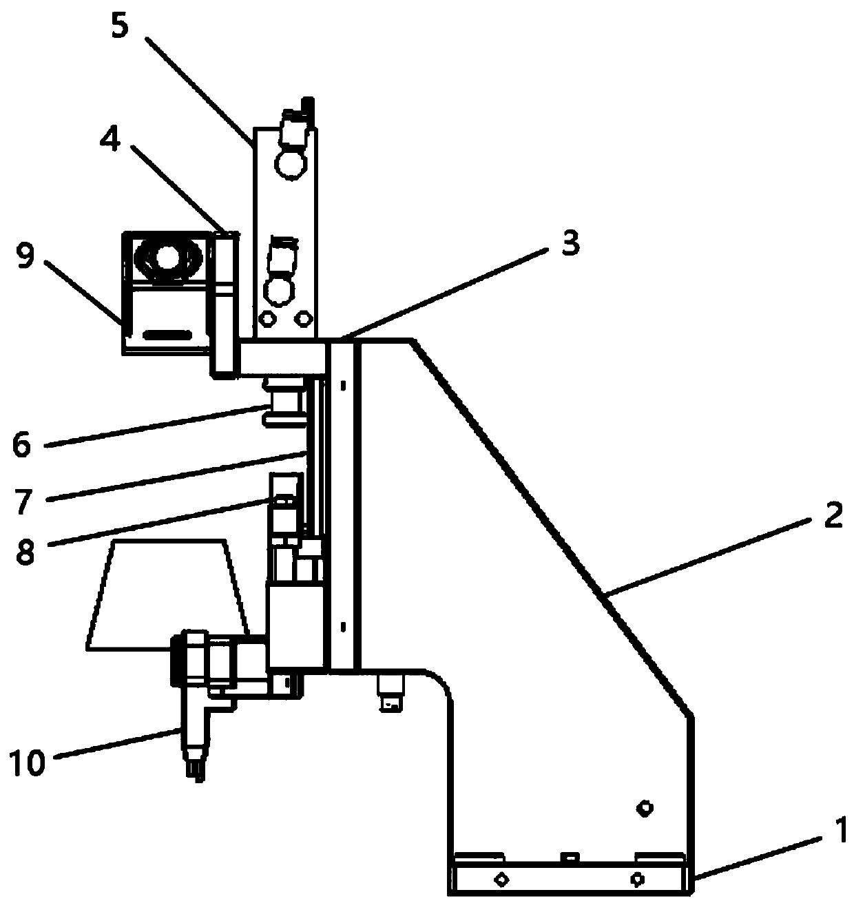
[0047] like figure 1 As shown in , it shows a perspective view of a connector PIN pin height measuring device; as figure 2 As shown, it shows a front view of a connector PIN pin height measuring device; as image 3 As shown in , it shows a right side view of a connector PIN pin height measuring device.

[0048] combine figure 1 , 2 As shown in , 3, a connector PIN pin height measuring device provided by the embodiment of the present application, the device includes a support unit, a power unit and a detection unit, and the structure of the support unit is a bracket with a base 1 for Carrying a detection unit and a power unit, the detection unit and the power unit are located on the bracket, the power unit is connected to the bracket to provide power for the detection unit, and the detection unit is connected ...

Embodiment 2

[0059] On the basis of Embodiment 1, this embodiment further proposes a method for using a connector PIN pin height measuring device. The same technical features and technical descriptions as Embodiment 1 will not be repeated in this embodiment.

[0060] combine figure 1 , 4 As shown, the method of using the connector PIN pin height measuring device is specifically:

[0061]Step 1: Integrate the connector PIN needle height measuring device into the production line for processing connectors with PIN needles, and the position of the height measuring device is in the downstream area of ​​the production line relative to the processing device for connectors with PIN needles;

[0062] Step 2: Before each PIN needle detection, supply air to the feed cylinder 5 to press it down. As the pressure in the cylinder gradually increases, the piston rod and the floating joint 6 will move downward together. Under the action of the thrust of the floating joint 6, the sub-carrier 8 slides alon...


PUM


Abstract

The invention discloses a connector PIN height measuring device. The connector PIN height measuring device comprises a support unit, a power unit and a detection unit, wherein the support unit is a support with a base and used for bearing the detection unit and the power unit, the detection unit and the power unit are located on the support, the power unit is connected with the support and used for providing power for the detection unit, and the detection unit is connected with the power unit and used for detecting the height of a PIN on the connector. The spring in the connector PIN height measuring device is compressed by the upward force of the conversion pin. The upward extending length of the conversion pin is equal to the reduced length of the spring due to compression, the multi-point laser displacement sensor can detect the upward extending length of the conversion pin, and whether the height of the connector PIN reaches the standard or not can be judged according to the upwardextending length.

Description

technical field [0001] The invention relates to the technical field of automatic manufacturing, in particular to a connector PIN needle height measuring device and a method for using the same. Background technique [0002] PIN needle is a metal substance used in connectors to complete electrical conduction and signal transmission. The raw material for making PIN needles is "tungsten carbide", which is hard alloy. Hard alloy has high hardness, strength and wear resistance. And corrosion resistance, known as "industrial teeth", widely used in military industry, aerospace, machining, metallurgy, oil drilling, mining tools, electronic communications, construction and other fields. In electronic products, a large number of connecting devices need to be used. These connecting devices usually need to use multiple PIN pins for connection. Pins are easy to break during the production process, especially when one or several PIN pins are broken, it is very difficult to find, and once ...

Claims


Application Information

Patent Timeline
Patent Type & Authority Applications(China)
IPC IPC(8): G01B11/06
CPCG01B11/0608
Inventor 张沁陆成博
Owner 苏州凌创科技发展有限公司
Why Eureka
Try Eureka