Spray collecting device

A collection device and collector technology, which is applied to the sampling device and other directions to achieve the effects of simple overall structure, good stability and simple structure

Pending Publication Date: 2018-12-21
JIANGSU UNIV OF SCI & TECH
View PDF0 Cites 3 Cited by
  • Summary
  • Abstract
  • Description
  • Claims
  • Application Information

AI Technical Summary

Problems solved by technology

[0003] The purpose of the present invention is to provide a spray collection device to solve the problem that the existing flow intensity device continues to collect abnormally distributed liquid after the nozzle is closed

Method used


Image

  • Spray collecting device
  • Spray collecting device
  • Spray collecting device

Examples


Embodiment Construction

[0026] The present invention will be further described below in conjunction with the accompanying drawings and specific embodiments, but the protection scope of the present invention is not limited thereto.

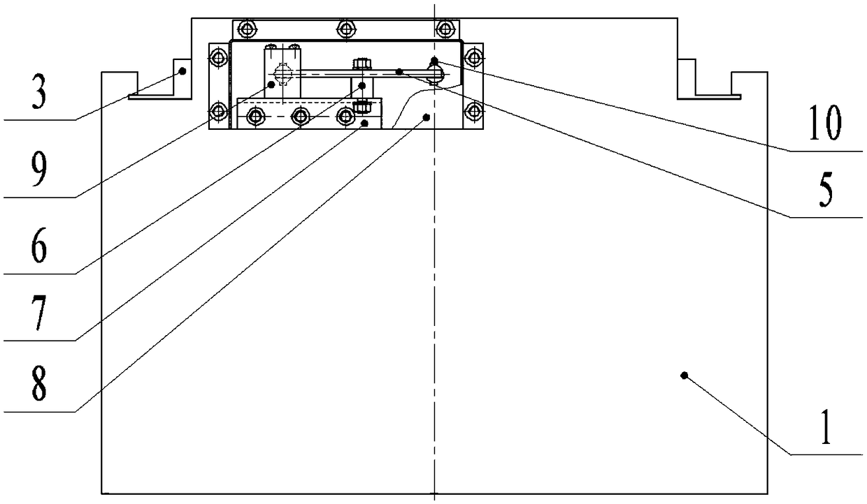
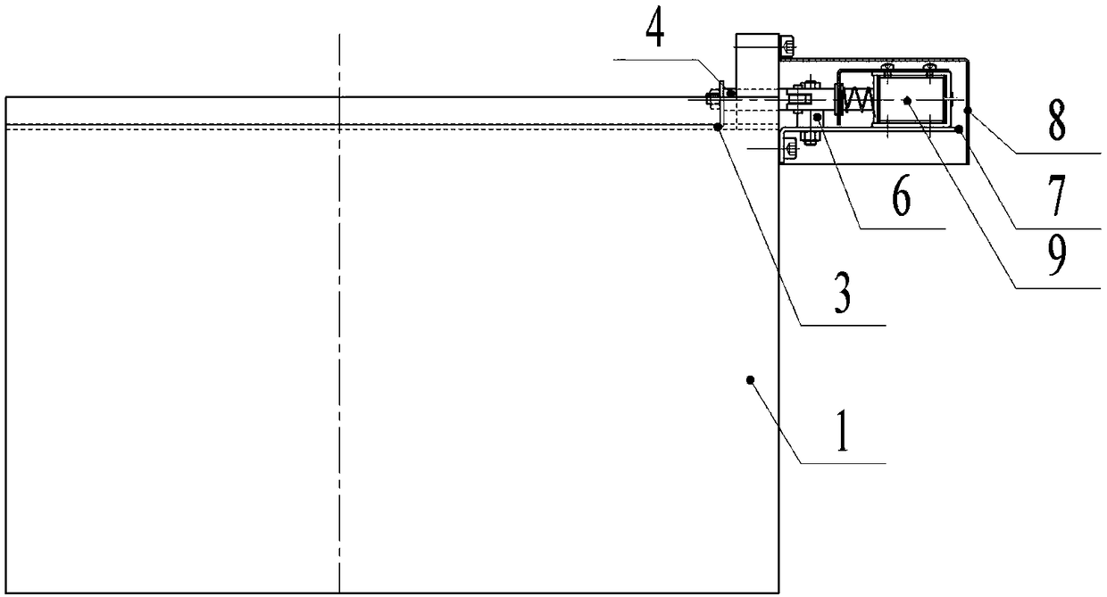
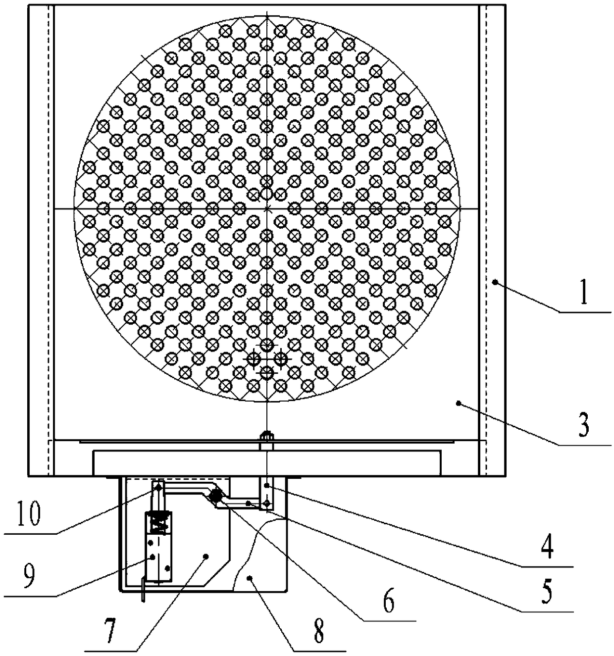
[0027] A spray collection device of the present invention, the main structure includes a collection chassis 1, a collector 2, a cover plate 3, a pull rod 4, a lever 5, a lever shaft 6, a waterproof box mounting plate 7, a waterproof box 8, an electromagnet 9, and a connecting pin 10.

[0028] like Figure 1 to Figure 3 As shown, the collection chassis 1 is the main part of the present invention, and is a left-right symmetrical square box. The collector 2 is installed inside the collection chassis 1 and can be taken out from the collection chassis 1 side. The card slot is located on the upper part of the collector 2, and fits with the collector 2, and can slide back and forth. Waterproof box mounting plate 7 is fixed on the side of collecting chassis 1, and electromagnet...


PUM


Abstract

The invention provides a spray collecting device. The spray collecting device comprises a collecting chassis, a collector, a cover plate, a pull rod, a lever, a lever rotating shaft, a waterproof boxmounting plate, a waterproof box, an electromagnet and a connection pin. The collecting chassis is a square box body; the collector is installed in the collecting chassis and can be taken out form oneside of the collecting chassis; and the cover plate is installed in a clamping groove of the collecting chassis, is positioned at the upper portion of the collector, is attached to the collector, andcan slide back and forth. The spray collecting device can avoid external interference in the collecting process, the problem that abnormally distributed liquid continues to flow into a liquid trap todisturb normal collection after a nozzle is opened and closed, the whole spray device is simple in structure, an experimental device is convenient to operate and adjust, manufacturing and maintenancecosts are low, the stability is good, the reliability is high, and the engineering application is facilitated.

Description

technical field [0001] The invention relates to the field of spray measurement, in particular to a spray collection device. Background technique [0002] With the advancement of technology, all walks of life are increasingly pursuing fine control of spray atomization performance, and the atomization performance of nozzles is not only measured by atomization fineness, spray angle and crushing length, but also by its flow intensity. Distribution is also an important indicator. In actual use, the collection method is often used to measure the flow intensity. Usually, the injector / nozzle is placed in the center of the circular surface of the liquid collector, and a group of liquid collectors are evenly distributed circumferentially or radially under the nozzle. During the measurement, the nozzle is controlled. The switch can obtain accurate measurement time, weigh the liquid collected by the liquid collector at a specified position within a period of time, and calculate the are...

Claims


Application Information

Patent Timeline
Patent Type & Authority Applications(China)
IPC IPC(8): G01N1/10
CPCG01N1/10
Inventor 陈晨郭家欣夏晶唐文献张建王筱蓉
Owner JIANGSU UNIV OF SCI & TECH
Why Eureka
Try Eureka