
Efficient detection device for fingerprint modules

A technology of detection device and fingerprint module, applied in the field of fingerprint identification, can solve problems such as low test efficiency, and achieve the effect of efficient test work

Inactive Publication Date: 2018-12-21
JIANGSU A KERR BIOLOGICAL RECOGNITION TECH CO LTD
View PDF9 Cites 0 Cited by
  • Summary
  • Abstract
  • Description
  • Claims
  • Application Information

AI Technical Summary

Problems solved by technology

[0003] In traditional production, fingerprint modules are tested in a single group, that is, the fingerprint modules on the entire board are disassembled group by group for testing, which is inefficient for testing.

Method used


Image

  • Efficient detection device for fingerprint modules
  • Efficient detection device for fingerprint modules
  • Efficient detection device for fingerprint modules

Examples


Embodiment 1

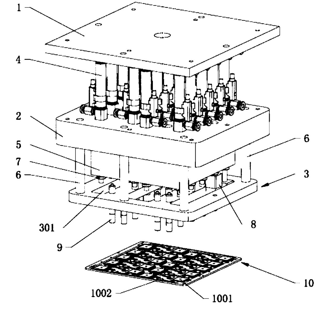
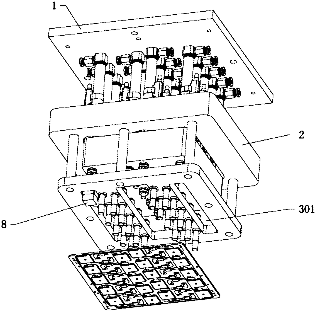
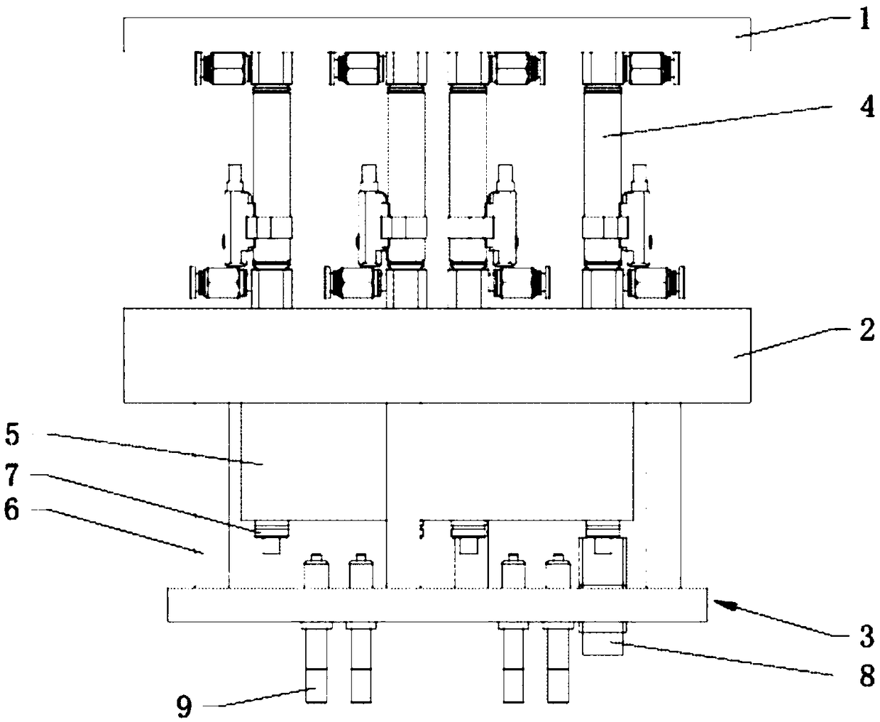
[0023] Embodiment 1: a kind of high-efficiency detection device for fingerprint module, such as Figure 1 ~ Figure 4 As shown, including pressure measurement device and frame;

[0024] The pressure measurement device includes, from top to bottom, a horizontally arranged first connecting plate, a horizontally arranged second connecting plate, and a horizontally arranged third connecting plate;

[0025] At least two vertically arranged first air cylinders are arranged between the first connecting plate and the second connecting plate, and the driving ends of the first air cylinders pass through the second connecting plate and extend to the second connecting plate below;

[0026] A connecting rod is provided between the second connecting plate and the third connecting plate, and the third connecting plate is provided with a test channel that runs through the upper surface of the third connecting plate and the lower surface of the third connecting plate. groove, the bottom of th...

Embodiment 2

[0035] Embodiment 2: An efficient detection device for a fingerprint module, including a pressure measurement device and a frame 11 . The pressure measurement device includes, from top to bottom, a horizontally arranged first connecting plate 1 , a horizontally arranged second connecting plate 2 and a horizontally arranged third connecting plate 3 . Between the first connecting plate 1 and the second connecting plate 2 there are 20 vertically arranged first air cylinders 4 , the driving ends of the first air cylinders 4 pass through the second connecting plate 2 and extend below the second connecting plate 2 . A connecting rod 6 is arranged between the second connecting plate 2 and the third connecting plate 3 , and the third connecting plate 3 is provided with a test through groove 301 that runs through the upper surface of the third connecting plate 3 and the lower surface of the third connecting plate 3 , The bottom of the third connecting plate 3 is provided with a thimble...


PUM


Abstract

The invention discloses an efficient detection device for fingerprint modules. The device comprises a pressure detection device and a framework, wherein the pressure detection device comprises a horizontally-arranged first connecting plate, a horizontally-arranged second connecting plate and a horizontally-arranged third connecting plate sequentially from top to bottom; a connecting rod is arranged between the second connecting plate and the third connecting plate, the third connecting plate is provided with a test through slot penetrating through the upper surface of the third connecting plate and the lower surface of the third connecting plate, and an ejector pin is arranged at the bottom of the third connecting plate; a vertically-arranged second cylinder is arranged above a transverseplate, and the driving end of the second cylinder penetrates through the transverse plate and extends above the first connecting plate to be connected with the first connecting plate; and the device also comprises a vertically-arranged guide rail, wherein the lower end of the guide rail is connected with the upper surface of the first connecting plate, and the upper end of the guide rail penetrates through the transverse plate and extends above the transverse plate. According to the device, through the arrangement of at least two first cylinders, testing of multiple fingerprint modules can bequickly completed.

Description

technical field [0001] The invention relates to an efficient detection device for a fingerprint module, belonging to the technical field of fingerprint identification. Background technique [0002] With the development of electronic technology, more and more mobile terminals have adopted fingerprint identification technology. Compared with traditional digital passwords or Jiugongge passwords, fingerprint recognition technology has better security, and fingerprint recognition technology has a faster experience. When the fingerprint module is produced, it is a whole board, which is called the fingerprint module frame, and there are many groups of fingerprint modules on one board. [0003] In traditional production, fingerprint modules are tested in a single group, that is, the fingerprint modules on the entire board are disassembled group by group for testing, which is inefficient. Therefore, there is a need for a device that can efficiently complete the testing work of the ...

Claims


Application Information

Patent Timeline
Patent Type & Authority Applications(China)
IPC IPC(8): G01R31/28
CPCG01R31/282G01R31/2829
Inventor 张成王丽位贤龙陈松姚燕杰
Owner JIANGSU A KERR BIOLOGICAL RECOGNITION TECH CO LTD
Learn More