
System and method for detecting and analyzing compositions

a composition and system technology, applied in the field of systems and methods for detecting compositions, can solve the problems of tbc system service life being typically limited, bond coat and substrate underlying the tbc are susceptible to corrosion attack

Inactive Publication Date: 2009-05-19
GENERAL ELECTRIC CO
View PDF6 Cites 36 Cited by
  • Summary
  • Abstract
  • Description
  • Claims
  • Application Information

AI Technical Summary

Benefits of technology

[0010]The system and method of this invention are preferably capable of rapid in-situ inspections and measurements performed on a component without causing life-limiting damage to the component. Inspection and analysis can be conducted during routine maintenance or inspection schedules when the turbomachine is not operating and is cool. Such inspections can be scheduled on the basis of the results of previous inspections and the operating conditions of the component since the previous inspection.

Problems solved by technology

The latter requirement is particularly demanding due to the different coefficients of thermal expansion (CTE) between ceramic materials and the substrates they protect, which are typically superalloys, though ceramic matrix composite (CMC) materials are also used.
The service life of a TBC system is typically limited by a spallation event driven by bond coat oxidation, increased interfacial stresses, and the resulting thermal fatigue.
As a result, during thermal cycling TBC spallation is likely to occur from the infiltrated and solidified CMAS interfering with the strain-tolerant nature of columnar TBC, particularly TBC deposited by PVD and APS due to the ability of the molten CMAS to penetrate their columnar and porous grain structures, respectively.
Another detriment of CMAS is that the bond coat and substrate underlying the TBC are susceptible to corrosion attack by alkali deposits associated with the infiltration of CMAS.
However, a complication is that confirmation of the presence of CMAS requires chemical analysis, which using conventional equipment would require removal of the component from the turbine.

Method used


Image

  • System and method for detecting and analyzing compositions
  • System and method for detecting and analyzing compositions
  • System and method for detecting and analyzing compositions

Examples


Embodiment Construction

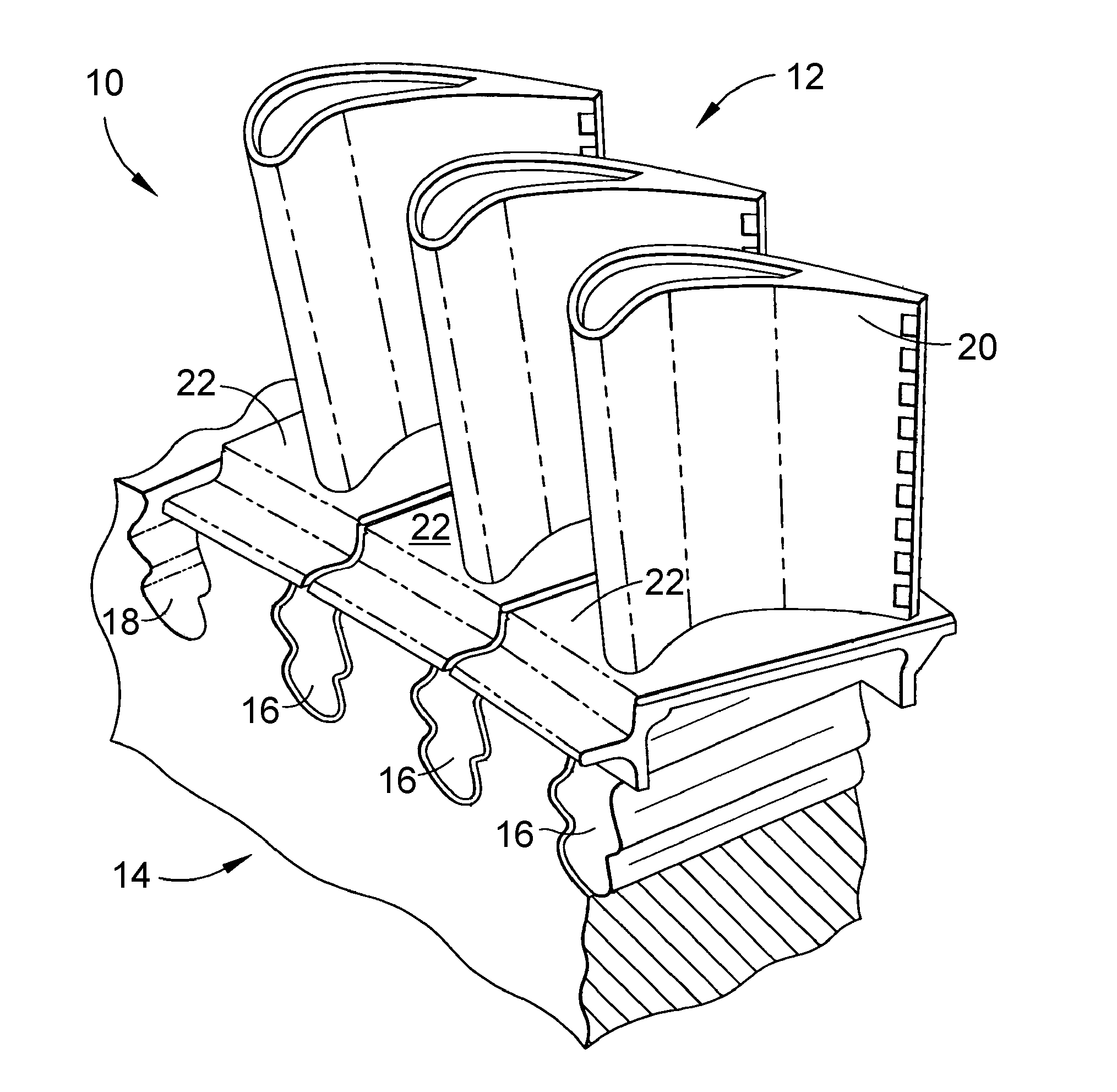
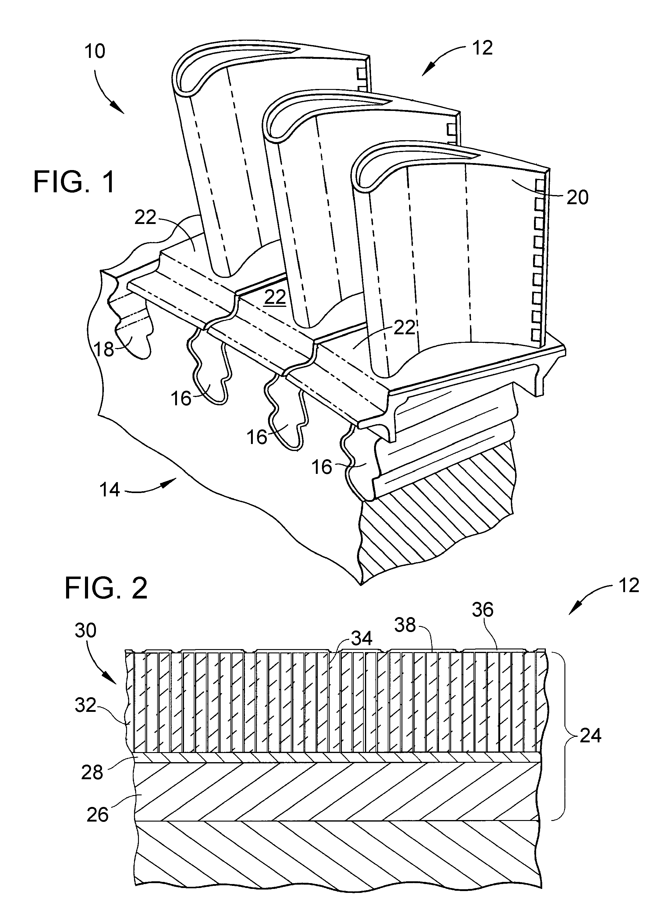
[0016]The present invention will be described in reference to turbine components of a turbomachine, including gas turbines used for power generation and propulsion, though it should be understood that the invention can be employed with a variety of components that operate within thermally and chemically hostile environments. For purposes of discussion, a fragment of a high pressure turbine assembly 10 is shown in FIG. 1. The turbine assembly 10 is generally represented as being of a known type, and includes high pressure turbine blades 12 mounted to a disk 14. The blades 12 may be formed of an iron, nickel or cobalt-base superalloy, with nickel-base superalloys typically being preferred. The blades 12 are individually anchored to the turbine disk 14 with dovetails 16 that interlock with dovetail slots 18 formed in the circumference of the disk 14. Each blade 12 has an airfoil 20 and platform 22 against which hot combustion gases are directed during operation of the turbomachine, and...


PUM


Abstract

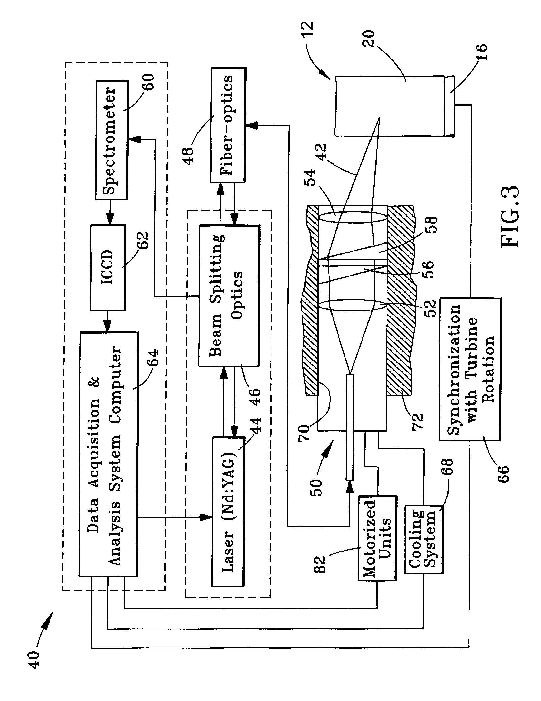
A system and method for performing laser plasma spectroscopy on a surface of a component, particularly to detect, analyze, and determine the extent of deposit build up on turbomachine components protected by coatings that are susceptible to damage from infiltration of deposits. The system includes a laser energy source and a probe interconnected with the laser energy source to receive a laser beam therefrom and then direct the laser beam onto the surface of the component and scan an area of the surface while the component remains stationary. The probe is further configured to collect radiation emitted from a laser-induced plasma generated by the laser beam at the surface of the component. The system is further equipped to transmit the radiation from the probe and spectrally analyze the radiation.

Description

BACKGROUND OF THE INVENTION[0001]This invention generally relates to systems and methods for detecting and analyzing compositions. More particularly, this invention is directed to a system and method for detecting, analyzing, and determining the extent of contaminant build up on components exposed to high temperatures, such as turbine components protected by coatings that are susceptible to damage by infiltration of contaminants in the operating environment of a turbomachine.[0002]Hot section components of turbomachines, including gas turbines employed for power generation and propulsion, are often protected by a thermal barrier coating (TBC) to reduce the temperature of the underlying component substrate and thereby prolong the service life of the component. Ceramic materials and particularly yttria-stabilized zirconia (YSZ) are widely used as TBC materials because of their high temperature capability, low thermal conductivity, and relative ease of deposition by plasma spraying, fl...

Claims


Application Information

Patent Timeline
IPC IPC(8): G01J3/30
CPCG01N21/718G01N21/94G01N21/9515G02B23/2423G02B26/108G01N2201/1056
Inventor VIERTL, JOHN RUEDIGER MADERNELSON, WARREN ARTHUR
Owner GENERAL ELECTRIC CO
Learn More