X-ray inspection apparatus for pipeline girth weld inspection

a technology of x-ray inspection and pipeline girth, which is applied in the direction of measuring devices, instruments, scientific instruments, etc., can solve the problems of increasing the time of pipe diameters, reducing the cycle time of rtr weld inspection systems, and requiring time-consuming and environmentally unfriendly chemical processing, etc., to achieve the elimination of increased pipe diameter, reduced cycle time of rtr weld inspection systems, and increased x-ray intensity levels at r

Active Publication Date: 2012-08-09
SHAWCOR LTD
View PDF12 Cites 37 Cited by
  • Summary
  • Abstract
  • Description
  • Claims
  • Application Information

AI Technical Summary

Benefits of technology

[0007]The use of such an arrangement enables a cycle time of RTR weld inspection systems to be decreased, particularly on larger pipelines of, for example, 24 inches diameter or more because the x-ray source is closer to the RTR detector. Smaller diameter pipelines radiography may also benefit from this invention.
[0008]By using this technique the x-ray intensity levels at the RTR detection system are increased significantly compared to a conventionally deployed panoramic x-ray source (e.g. by ten times on a 48 inch diameter pipe) and the effects of the inverse square or flux reduction with increased pipe diameter are eliminated. The scanning speed of the RTR detector at a constant wall thickness is related only to the pipeline circumference. This enables large diameter pipe circumferential welds to be rapidly inspected with a single RTR detector which scans around a weld in synchronism with an x-ray source on a suitable x-ray crawler.

Problems solved by technology

Use of x-ray film requires times consuming and environmentally unfriendly chemical processing, washing and drying prior to the production of an image which can be viewed and stored.
However, their applications are typically limited to pipe diameters of 24 inches or less, as inspection times on larger diameters increase rapidly.
The result of this is that on medium to large diameter pipes, the x-ray flux is of such a reduced level that inspection with RTR detectors is unacceptably slow and therefore not commercially viable.

Method used


Image

  • X-ray inspection apparatus for pipeline girth weld inspection
  • X-ray inspection apparatus for pipeline girth weld inspection
  • X-ray inspection apparatus for pipeline girth weld inspection

Examples


Embodiment Construction

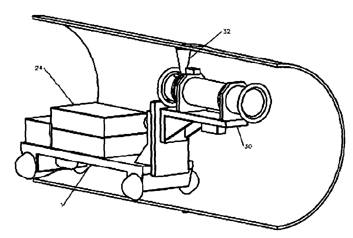
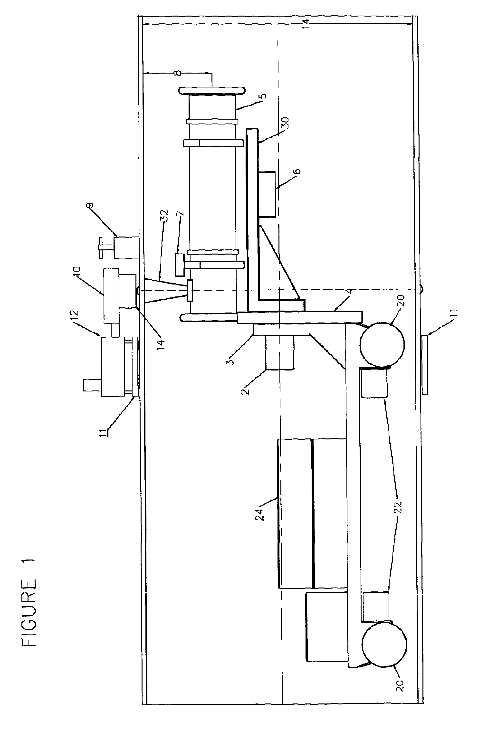
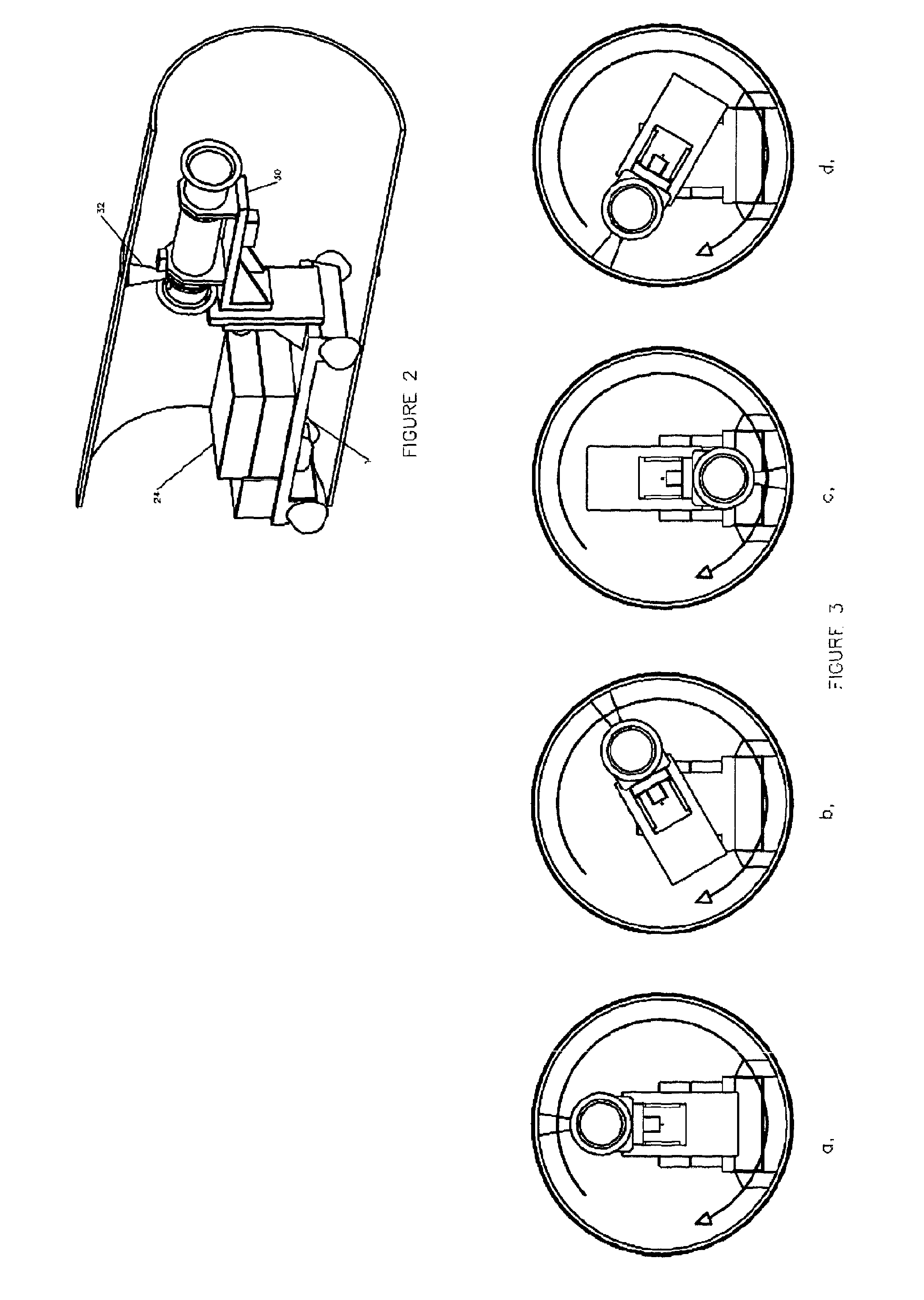
[0014]The apparatus comprises a conventional crawler chassis (1) as shown in FIG. 1 and 2 of the type used in prior art systems. This consists of a main chassis body, motor / gearbox drives 22 and drive wheels at the front and back, a battery box 24 for powering the x-ray source and the motors. The crawler is controlled by an electrical control panel that contains the x-ray controller, programmable logic controller (PLC), motor drives and interfaces.

[0015]The chassis front differs from conventional designs in that it includes a strong mounting point for an offset rotate mechanism. This mechanism, by way of example, comprises a rotate gear motor (2) supported in a strong frame (3) securely fixed to the crawler chassis. The gear motor shaft is fixed to a rotatable member or disk (4).

[0016]The rotatable member (4) has an offset mounted support cradle (30) for carrying an x-ray source (5). This support cradle also carries an inclinometer (6) and a gamma ray detector (7). A height adjustme...


PUM

PropertyMeasurementUnit
diametersaaaaaaaaaa
diameteraaaaaaaaaa
diameteraaaaaaaaaa

Abstract

An apparatus is provided for x-ray inspection of a pipeline girth weld. This comprises a directional x-ray source 5 which is insertable into a pipeline section and is rotatable within the pipeline. Means are provided to align the directional x-ray source with an external x-ray detector such that both may be rotated through 360 degrees substantially coaxially with the pipeline section. Means for sampling the data detected by the x-ray detector are provided so that it may be further analysed.

Description

FIELD OF THE INVENTION[0001]This invention relates to an x-ray inspection apparatus and method for pipeline girth weld inspection.BACKGROUND OF THE INVENTION[0002]It is well known in the art that pipeline girth (circumferential) welds are often inspected with radiography using a conventional x-ray crawler in conjunction with either x-ray film or real-time radiographic (RTR) detectors. These crawlers are used when access can be easily made to an open end of a pipeline section which is being welded to another pipeline section. The x-ray crawler comprises an x-ray source on a crawler or buggy which can be driven into the open end of the pipeline and which will crawl along the pipeline to the area of the circumferential weld.[0003]The x-ray source is panoramic and mounted to be substantially central within the pipe and omits x-rays around a 360 degree arc around the weld surface. This type of x-ray source is generally used with x-ray film and is suitable for most pipe diameters.[0004]Us...

Claims


Application Information

Patent Timeline
Patent Type & Authority Applications(United States)
IPC IPC(8): G01N23/02
CPCG01N2223/628G01N23/18G01N23/083
Inventor KNIGHT, STEPHENDRAKE, STEPHEN G.
Owner SHAWCOR LTD
Why Eureka
Try Eureka