Low power consumption device battery life test system and test method

A battery life and test method technology, applied in the direction of measuring electricity, measuring devices, measuring electrical variables, etc., to achieve the effect of convenient assembly, accurate battery life data, and simple composition

Pending Publication Date: 2018-12-21
XIAMEN INTRETECH
View PDF6 Cites 0 Cited by
  • Summary
  • Abstract
  • Description
  • Claims
  • Application Information

AI Technical Summary

Problems solved by technology

[0005] The problem to be solved by the present invention is to provide a battery life testing system and testing method for low power consum

Method used


Image

  • Low power consumption device battery life test system and test method

Examples


Embodiment Construction

[0019] Existing battery life testing systems and methods for low power consumption devices cannot accurately perform corresponding battery life testing.

[0020] Therefore, the present invention provides a new battery life testing system and method for low power consumption devices to solve the above-mentioned shortcomings.

[0021] For a clearer representation, the present invention will be described in detail below in conjunction with the accompanying drawings.

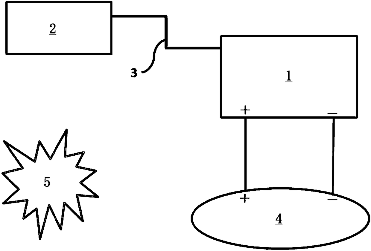
[0022] An embodiment of the present invention provides a battery life testing system for low-power devices, including a DC power analyzer 1 and a computer 2, and of course the tested low-power device 4, that is, these three constitute the main part of the system. Wherein, the computer 2 and the DC power analyzer 1 are connected through a data line 3 .

[0023] The DC power analyzer 1 is electrically connected to the tested low power consumption device 4 . Because, the DC power analyzer 1 is used to supply power to...


PUM


Abstract

The invention relates to a low power consumption device battery life test system and test method. The test system comprises a DC power analyzer and a computer. A power output port of the DC power analyzer is electrically connected with a power input end of a tested low power consumption device; the DC power analyzer is used for powering the tested low power consumption device; and the computer isconnected with the DC power analyzer via a data line. The test system improves the accuracy of test results for battery life of the low power consumption device.

Description

technical field [0001] The invention relates to the field of batteries, in particular to a battery life testing system and testing method for low power consumption equipment. Background technique [0002] For low-power devices, they are usually powered directly by a battery, and the life of the battery determines the working time of the device. Therefore, it is very critical to accurately test the battery life, especially for more and more low-power devices in the Internet of Things. If the battery life test is inaccurate, the corresponding device may not be able to connect to the network, resulting in various adverse consequences. [0003] The existing test method for the battery life of low-power devices is to use an oscilloscope with a current probe to trigger the terminal device (low-power device) to report the status, capture the single-time power consumption by instantaneous working current, and calculate the power consumption for a day (For example, triggering 20 tim...

Claims


Application Information

Patent Timeline
IPC IPC(8): G01R31/36
Inventor 黄和聪钟扬贵吴连德
Owner XIAMEN INTRETECH
Why Eureka
Try Eureka