
A display panel and a display device

A technology for display panels and substrates, used in instruments, nonlinear optics, optics, etc., can solve problems such as electrical connection failure, large size, and increased risk of light leakage, reducing size, avoiding light leakage, and increasing available space. The effect of the area

Active Publication Date: 2021-06-18
SHANGHAI TIANMA MICRO ELECTRONICS CO LTD
View PDF4 Cites 0 Cited by
  • Summary
  • Abstract
  • Description
  • Claims
  • Application Information

AI Technical Summary

Problems solved by technology

In the prior art, silver glue dots are arranged at the step position formed by the color filter substrate and the array substrate. When the step area is bent to the side away from the light-emitting surface of the display panel, the bending axis will pass through the silver glue dot and the connecting pad. In the connection area, it is easy to cause the silver glue point to separate from the connection pad, making the electrical connection invalid
On the other hand, the height of the silver glue dots cannot be higher than the polarizer, so as not to affect the flatness of the surface of the flexible display panel near the light-emitting surface, and because the silver glue dots cannot be bent to the side away from the light-emitting surface of the flexible display panel, making The size of the lower frame of the flexible display device is relatively large, which is not conducive to narrowing the frame of the flexible display device
In addition, in order to avoid the poor display of the flexible display panel caused by the contact between the silver glue dots and the black matrix, the black matrix needs to be retracted, resulting in an increased risk of light leakage

Method used


Image

  • A display panel and a display device
  • A display panel and a display device
  • A display panel and a display device

Examples


Embodiment Construction

[0033] In order to further explain the technical means and functions adopted by the present invention to achieve the intended purpose of the invention, the specific implementation, structure, and features of a display panel and a display device proposed according to the present invention will be described below in conjunction with the accompanying drawings and preferred embodiments. And its effect, detailed description is as follows.

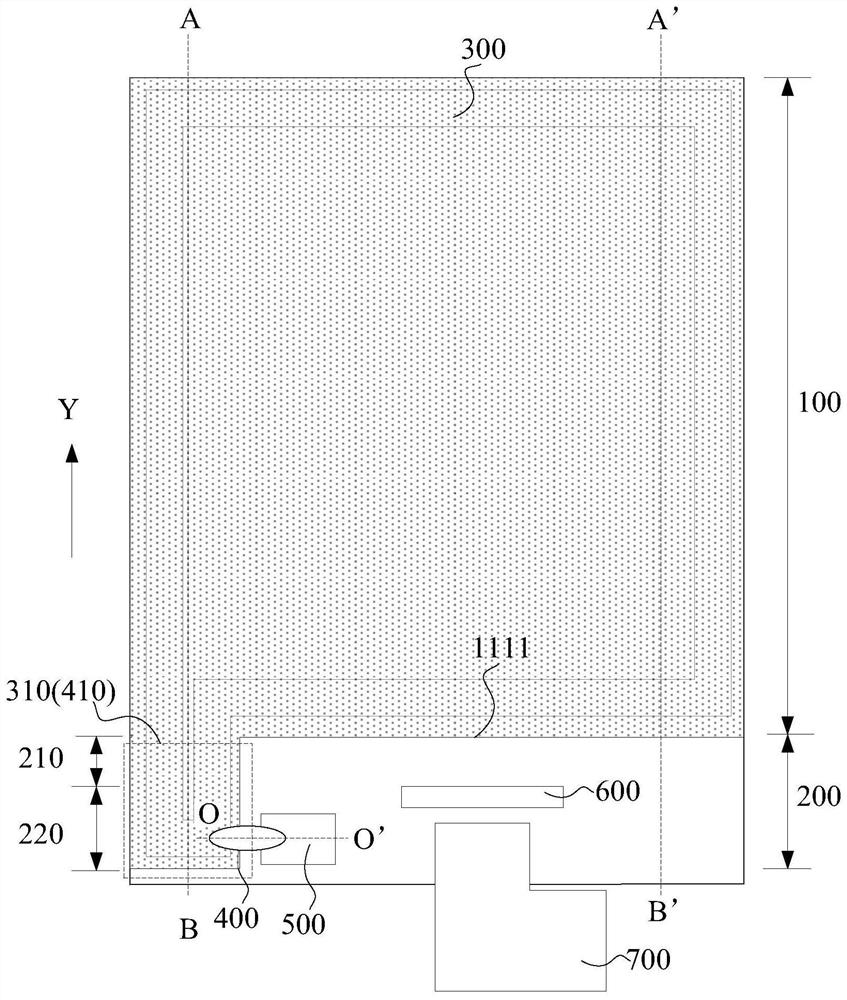
[0034] An embodiment of the present invention provides a display panel, including:

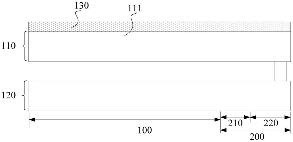
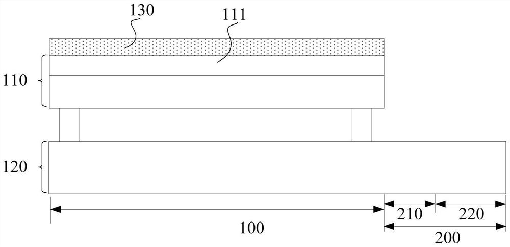
[0035] Relatively arranged flexible array substrate and flexible color filter substrate;

[0036] The display panel further includes a main body area and a step area, the main body area and the step area are arranged along a first direction; the step area includes a bending area and a non-bending area, and the bending area and the non-bending area The bending area is arranged along the first direction;

[0037] The flexible color filter substrate includes a fl...


PUM


Abstract

The invention discloses a display panel and a display device. The flexible color filter substrate of the display panel includes a flexible substrate, and at least one protruding structure extends from the side of the flexible substrate close to the step area, and the part of the flexible substrate except the at least one protruding structure is located in the main body area, and the protruding The structure extends toward the non-bending area through the bending area; the flexible color filter substrate also includes an electrostatic transmission layer, and the shape of the electrostatic transmission layer is the same as that of the flexible substrate; at least one One-to-one connection pads corresponding to the protruding structures; the connection pads are electrically connected to the electrostatic transport layer on the corresponding protruding structures through at least one connecting component. The technical solution provided by the embodiment of the present invention avoids the occurrence of the problem of conductive failure, so that the height of the connecting parts will not be affected by the height of the polarizer, reduces the size of the lower frame of the assembled display device, and avoids the black matrix shrinkage caused by occurrence of light leakage.

Description

technical field [0001] Embodiments of the present invention relate to display technologies, and in particular, to a display panel and a display device. Background technique [0002] With the continuous development of electronic technology, users have higher and higher requirements for the miniaturization of portable electronic products, and the advantages of flexible display panel's bendable characteristics are highlighted, which has become a recent research hotspot. [0003] In order to avoid electrostatic damage to the devices inside the flexible display panel, the flexible display panel is provided with an electrostatic transmission layer on the side of the color filter substrate away from the array substrate, and is electrically connected to the electrostatic transmission layer and the corresponding arrangement on the array substrate in the stepped area through silver glue points. The connection pads of the above-mentioned structure lead out the static electricity. In t...

Claims


Application Information

Patent Timeline
Patent Type & Authority Patents(China)
IPC IPC(8): G02F1/1333G02F1/1335G02F1/1362
CPCG02F1/133305G02F1/133514G02F1/136204G02F2202/22
Inventor 黄贤军
Owner SHANGHAI TIANMA MICRO ELECTRONICS CO LTD
Features
  • Generate Ideas
  • Intellectual Property
  • Life Sciences
  • Materials
  • Tech Scout
  • Unparalleled Data Quality
  • Higher Quality Content
  • 60% Fewer Hallucinations
Learn More