
Backlight module

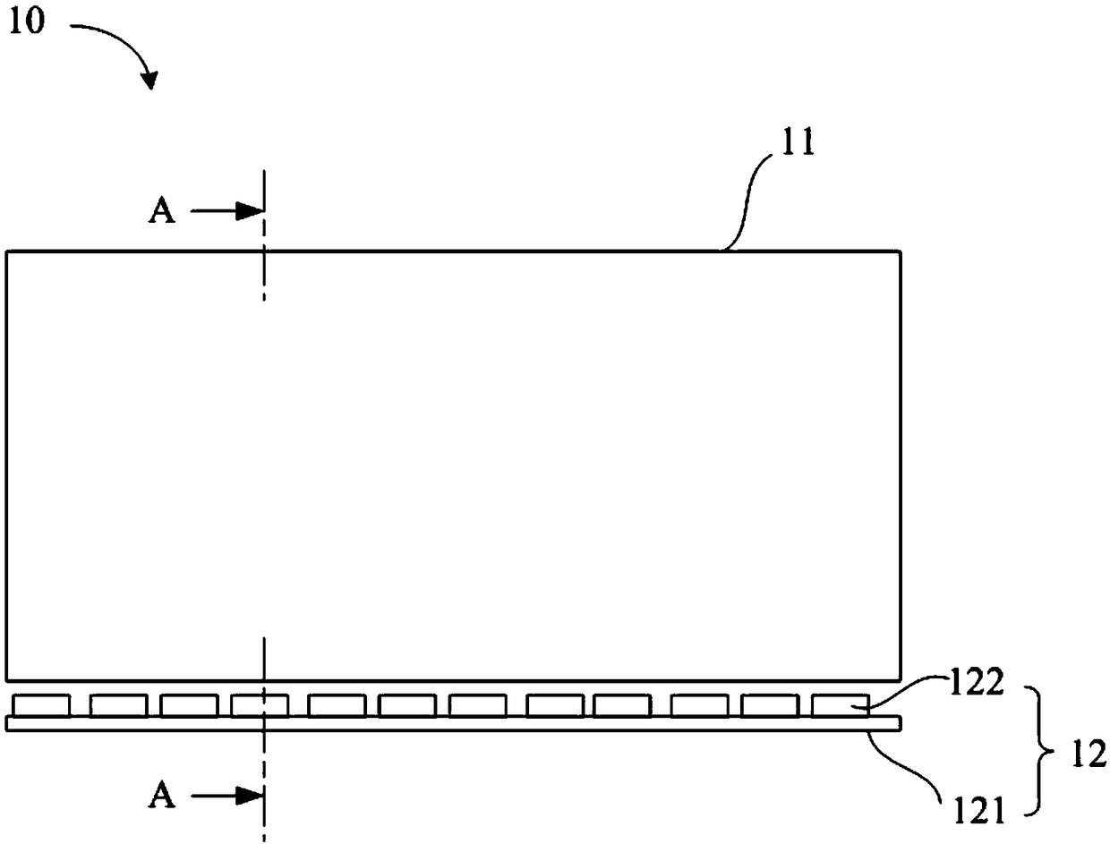
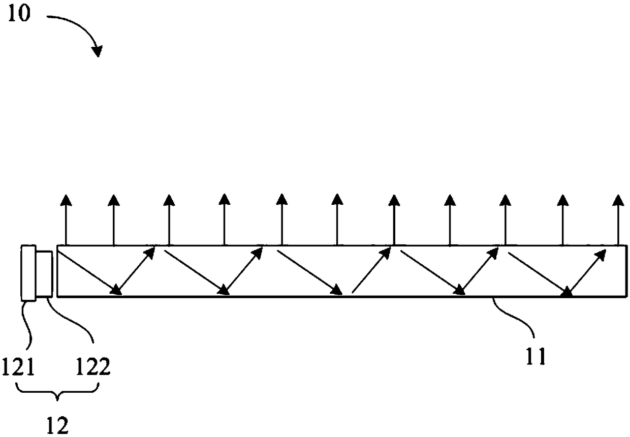
A technology of backlight module and light source module, which is applied in the direction of light guides, optics, optical components, etc., and can solve the problems of being unable to reduce the area of ​​the light guide plate 11 and the number of LED lamps 122

Inactive Publication Date: 2018-12-21
HUIZHOU CHINA STAR OPTOELECTRONICS TECHNOLOGY CO LTD
View PDF3 Cites 0 Cited by
  • Summary
  • Abstract
  • Description
  • Claims
  • Application Information

AI Technical Summary

Problems solved by technology

That is to say, this design cannot reduce the area of ​​the light guide plate 11 and reduce the number of LED lamps 122

Method used


Image

  • Backlight module
  • Backlight module
  • Backlight module

Examples


Embodiment Construction

[0022] In order to make the above and other objectives, features, and advantages of the present disclosure more comprehensible, preferred embodiments of the present disclosure will be exemplified below in detail with reference to the attached drawings.

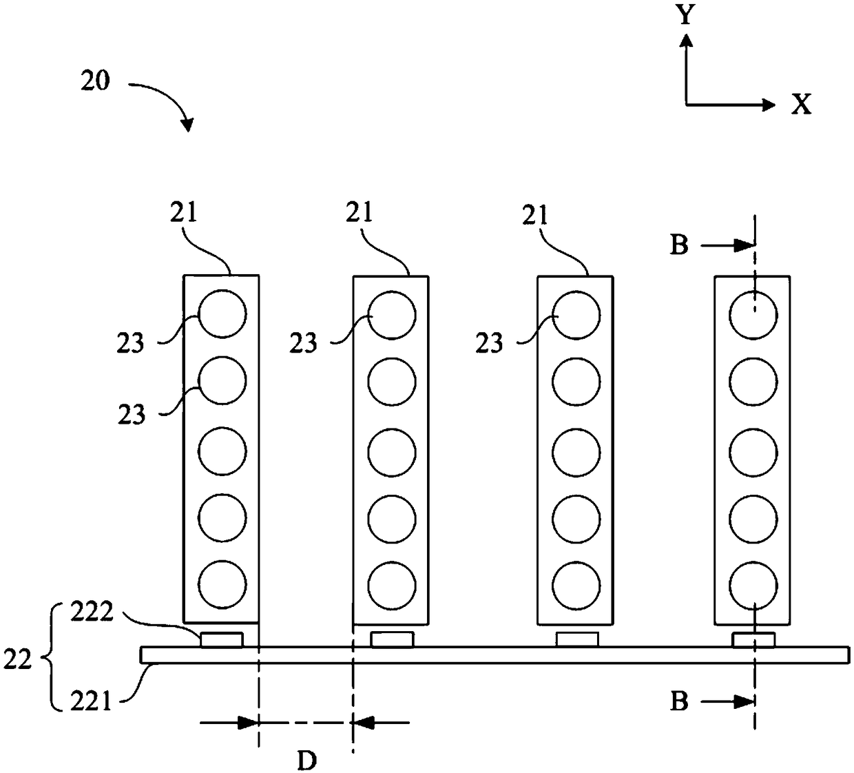
[0023] Please refer to image 3 , which shows a schematic diagram of a backlight module 20 according to a preferred embodiment of the present disclosure. The backlight module 20 can be applied to various suitable displays to provide sufficient brightness and evenly distributed light for the display to display images normally. The backlight module 20 includes a plurality of light guide strips 21 , a light source module 22 , and a plurality of scattering components 23 . The light guide strips 21 are elongated, and a plurality of light guide strips 21 are arranged in parallel in a row, that is, arranged in parallel and at intervals along the first direction (X direction), and two adjacent light guide strips 21 are separated by a...


PUM


Abstract

The invention provides a backlight module. The backlight module comprises a light source module, a plurality of light guide bars and a plurality of scattering parts, wherein the light source module isused for emitting a plurality of dot lights; each light guide bar contains one incident side and an outgoing side, the incident side is aligned with the corresponding dot light in the light source module so as to convert the dot light into linear light; and the scattering parts are arranged on the outgoing side of the light guide bars and used for making the light guided out from the light guidebars irradiate to the outside, wherein the plurality of light guide bars are arranged in parallel at intervals along a first direction.

Description

technical field [0001] The disclosure relates to a backlight module, in particular to a backlight module for a display. Background technique [0002] In recent years, due to the advantages of low power consumption, high brightness and good color saturation, liquid crystal displays (LCDs) have been widely used in various modern electronic products, such as personal computers, digital cameras, smart phones, etc. Mobile phones, tablet computers, LCD TVs, etc. A liquid crystal display is assembled from multiple components, and the backlight module is a key component of the liquid crystal display, which affects the overall power consumption, brightness and color saturation of the liquid crystal display. [0003] At present, the LCD backlight module mainly adopts the side-type or direct-type design to reduce the number of light-emitting diodes (light-emitting diodes, referred to as LEDs) used, thereby achieving energy-saving and cost-saving effects. However, no matter what kind ...

Claims


Application Information

Patent Timeline
Patent Type & Authority Applications(China)
IPC IPC(8): G02F1/13357G02B6/00
CPCG02F1/133615G02B6/0051
Inventor 郑净远
Owner HUIZHOU CHINA STAR OPTOELECTRONICS TECHNOLOGY CO LTD
Learn More