Motor shaft reduce mechanism

A deceleration mechanism and motor shaft technology, applied in electrical components, electromechanical devices, electric components, etc., can solve the problems of unstable motor operation, shortened motor service life, motor shaft failure, etc., achieve significant deceleration effect, eliminate inertial rotation, Small footprint effect

Active Publication Date: 2018-12-21
CHANGZHOU DENGFENG ELECTRICAL
View PDF4 Cites 3 Cited by
  • Summary
  • Abstract
  • Description
  • Claims
  • Application Information

AI Technical Summary

Problems solved by technology

[0002] The existing motor itself generally does not have a deceleration mechanism. Therefore, after the motor rotates at high speed and is powered off, due to the existence of inertia, the motor will continue to rotate for a period of time. It needs to rely on the frictional resistance of the motor itself to stop, and the deceleration effect is relatively poor.
And the motor shaft does not have self-locking ability, so it cannot be used in working conditions that require self-locking requirements
[0003] The deceleration of the motor shaft or the braking of the motor with a reduction mechanism generally adopts the method of locking brakes. A plurality of circularly distributed friction plates are arranged on the outer peripheral surface of the motor shaft. By applying radial force to the friction plates, the friction plates Hold it tightly on the outer peripheral surface of the motor shaft to realize the deceleration or braking effect of the motor shaft. This method has two disadvantages: ①The motor is large in size, and the installation of the friction plate will inevitably occupy the internal space of the motor, resulting in an increase in the volume of the motor and cost High, not easy to use the motor, ② easy to cause motor shaft failure, the friction plate will wear the surface of the motor shaft, will cause the axial runout of the motor shaft, cause the motor to run unstable, shorten the service life of the motor, and affect the normal use of the motor

Method used


Image

  • Motor shaft reduce mechanism
  • Motor shaft reduce mechanism
  • Motor shaft reduce mechanism

Examples


Embodiment 1

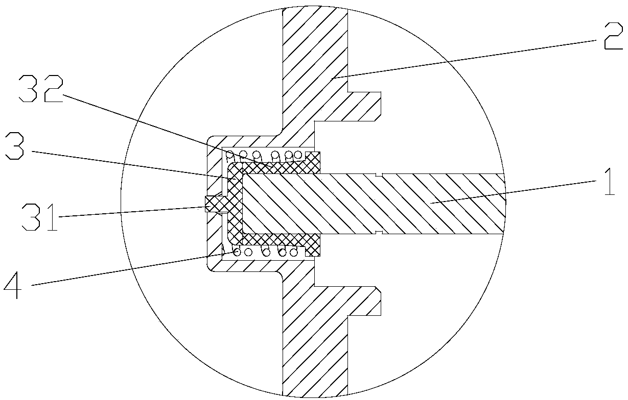
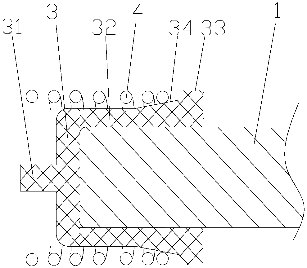
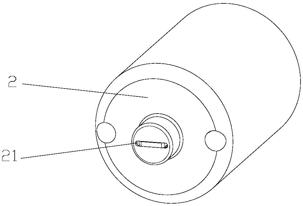
[0032] Embodiment 1: refer to Figure 1-Figure 3 , a motor shaft reduction mechanism, including a motor shaft 1, a motor rear end cover 2, a friction sleeve 3 in contact with the end surface of the motor shaft 1 is provided at the end of the motor shaft 1, and the friction sleeve 3 is made of a polymer wear-resistant material , the friction sleeve 3 is arranged at the end of the motor rear end cover 2 corresponding to the motor shaft 1, and the end surface of the friction sleeve 3 close to the motor rear end cover 2 is provided with a straight positioning protrusion 31 protruding toward the motor rear end cover 2, The corresponding position of the motor rear end cover 2 is provided with a positioning groove 21 that matches the positioning protrusion 31 and is consistent with the positioning protrusion 31. The positioning protrusion 31 snaps into the positioning groove 21 to realize the positioning of the motor rear end cover 2 to the friction sleeve 3 , to prevent the friction...

Embodiment 2

[0033] Embodiment 2: refer to figure 1 , Figure 4, a motor shaft reduction mechanism, including a motor shaft 1, a motor rear end cover 2, a friction sleeve 3 in contact with the end surface of the motor shaft 1 is provided at the end of the motor shaft 1, and the friction sleeve 3 is made of a polymer wear-resistant material , the friction sleeve 3 is arranged at the end of the motor rear end cover 2 corresponding to the motor shaft 1, and the end surface of the friction sleeve 3 close to the motor rear end cover 2 is provided with a straight positioning protrusion 31 protruding toward the motor rear end cover 2, The corresponding position of the motor rear end cover 2 is provided with a positioning groove 21 that matches the positioning protrusion 31 and is consistent with the positioning protrusion 31. The positioning protrusion 31 snaps into the positioning groove 21 to realize the positioning of the motor rear end cover 2 to the friction sleeve 3 , to prevent the fricti...

Embodiment 3

[0034] Embodiment 3: refer to figure 1 , a motor shaft reduction mechanism, including a motor shaft 1, a motor rear end cover 2, a friction sleeve 3 in contact with the end surface of the motor shaft 1 is provided at the end of the motor shaft 1, and the friction sleeve 3 is made of a polymer wear-resistant material , the friction sleeve 3 is arranged at the end of the motor rear end cover 2 corresponding to the motor shaft 1, and the end surface of the friction sleeve 3 close to the motor rear end cover 2 is provided with a straight positioning protrusion 31 protruding toward the motor rear end cover 2, The corresponding position of the motor rear end cover 2 is provided with a positioning groove 21 that matches the positioning protrusion 31 and is consistent with the positioning protrusion 31. The positioning protrusion 31 snaps into the positioning groove 21 to realize the positioning of the motor rear end cover 2 to the friction sleeve 3 , to prevent the friction sleeve 3 ...


PUM


Abstract

The invention relates to the technical field of electric machines, in particular to a motor shaft reduction mechanism including a motor shaft, a motor rear end cover, The motor shaft end part is provided with a friction sleeve which is in contact with the motor shaft end face, the friction sleeve is connected with the motor rear end cover, an elastic member which causes the friction sleeve to be attached on the motor shaft end face is arranged between the motor rear end cover and the friction sleeve, the end face is frictionally, and the motor shaft has self-locking force under the power-off state, the rotational inertia is eliminated, and the effect of decelerating or stopping rotation is good.

Description

technical field [0001] The invention relates to the technical field of motors, in particular to a motor shaft stop reduction mechanism. Background technique [0002] The existing motor itself generally does not have a deceleration mechanism. Therefore, after the motor rotates at high speed and is powered off, due to the existence of inertia, the motor will continue to rotate for a period of time. It needs to rely on the frictional resistance of the motor itself to stop, and the deceleration effect is relatively poor. Moreover, the motor shaft does not have self-locking capability, so it cannot be used under working conditions that require self-locking requirements. [0003] The deceleration of the motor shaft or the braking of the motor with a reduction mechanism generally adopts the method of locking brakes. A plurality of circularly distributed friction plates are arranged on the outer peripheral surface of the motor shaft. By applying radial force to the friction plates, ...

Claims


Application Information

Patent Timeline
Patent Type & Authority Applications(China)
IPC IPC(8): H02K7/102
CPCH02K7/102
Inventor 符德胜孙科
Owner CHANGZHOU DENGFENG ELECTRICAL
Why Eureka
Try Eureka