
Method for machining workpieces and grinding machine

A technology for grinding machines and workpieces, which is applied to machine tools, machine control programs of grinding machines, grinding machines, and grinding processing fields for shaft components used in vehicle drive devices to achieve the effect of improving accuracy

Inactive Publication Date: 2018-12-21
SCHAUDT MIKROSA
View PDF11 Cites 2 Cited by
  • Summary
  • Abstract
  • Description
  • Claims
  • Application Information

AI Technical Summary

Problems solved by technology

Preferably, this method can also be used in existing machine tools with little effort

Method used


Image

  • Method for machining workpieces and grinding machine
  • Method for machining workpieces and grinding machine
  • Method for machining workpieces and grinding machine

Examples


Embodiment Construction

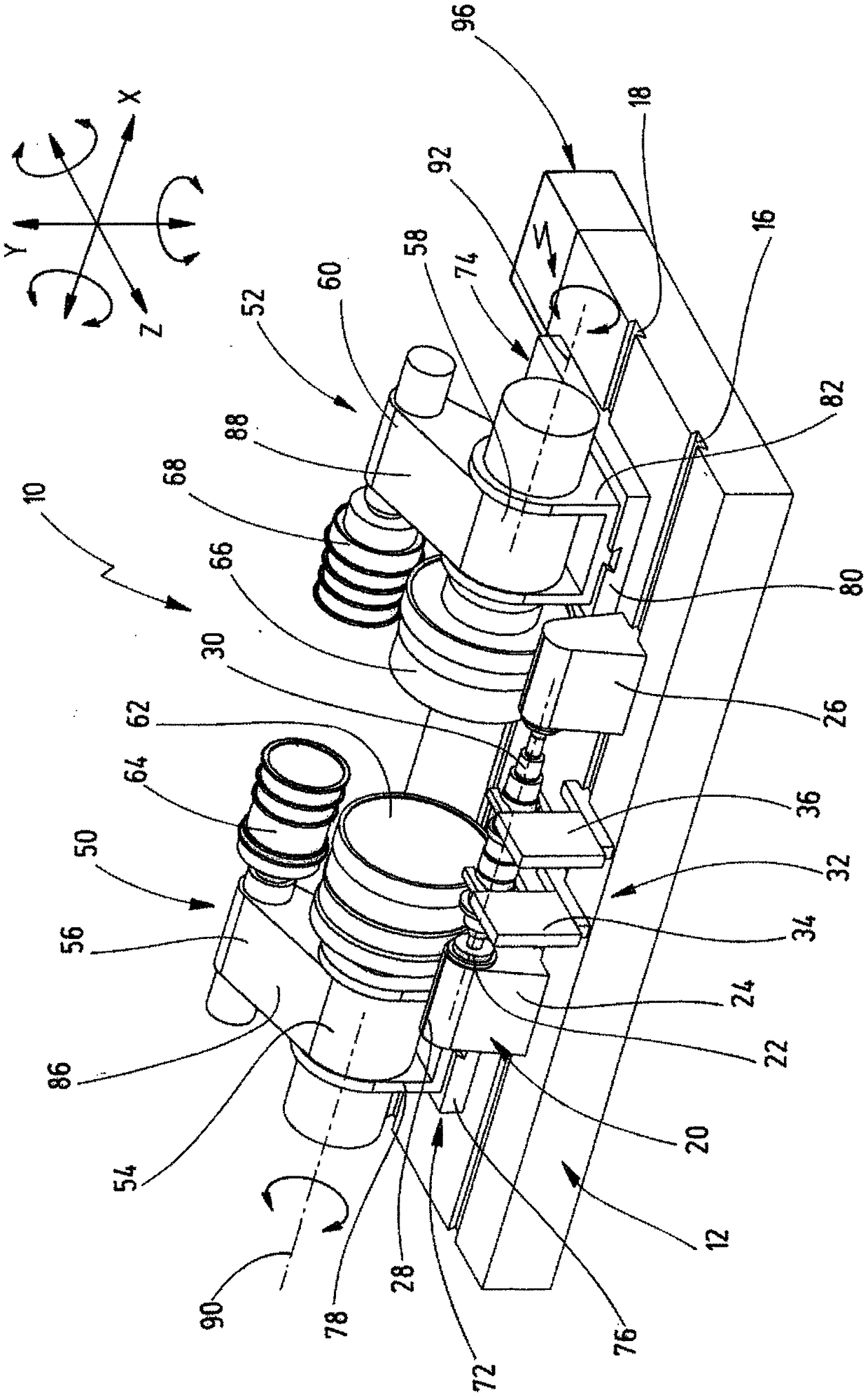
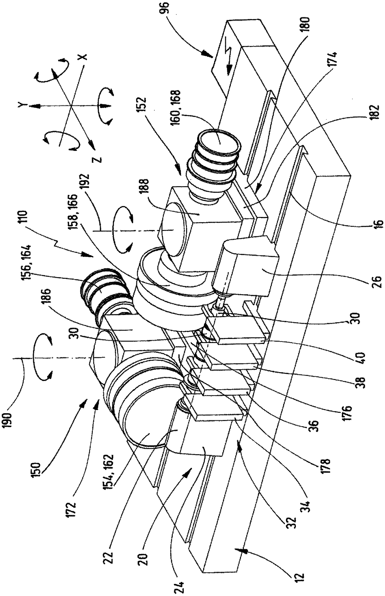
[0087] figure 1 A schematic perspective view of a power tool 10 , which is designed as a grinding machine, is shown.

[0088] The grinding machine 10 has a machine tool 12 which can also be referred to as a machine frame. Guides 16 , 18 are formed on the machine tool 12 . Components of the grinding machine 10 can be moved along the guides 16 , 18 and optionally fixedly arranged.

[0089] In at least some of the figures shown here, for purposes of illustration, coordinate systems are shown. Usually, the longitudinal direction is marked with an X. The horizontal direction is marked with Z. Vertically marked with Y. In this way, three translational or rectilinear axes X, Y and Z are defined. Respective rotations about axes X, Y and Z define respective axes of rotation. It goes without saying that, for illustration purposes, alternative coordinate systems, such as a machine coordinate system and / or a workpiece coordinate system, are also conceivable. The required imaginary...


PUM


Abstract

The invention relates to a grinding machine (10, 110) and to a method for machining workpieces (30) with wave-like shapes, in particular for grinding treatment, comprising the steps: receiving a workpiece (30) with a wave-like shape on a workpiece spindle (22); providing a group of steady rests (34, 36, 38, 40) which are spaced apart from one another along an axial longitudinal extension of the workpiece (30), wherein the steady rests (34, 36, 38, 40) can assume an engaged state and a non-engaged state, wherein the steady rests (34, 36, 38, 40) supportingly engage on the workpiece (30) in theengaged state; providing at least one grinding spindle (54, 56, 58, 60; 154, 156, 158, 160) with at least one grinding tool (62, 64, 66, 68; 162, 164, 166, 168); and machining the workpiece (30), comprising: generating an infeed movement to bring the grinding tool (62, 64, 66, 68; 162, 164, 166, 168) into engagement with the workpiece (30); generating a relative rotation between the grinding tool(62, 64, 66, 68; 162, 164, 166, 168) and the workpiece (30); and controlling the group of steady rests (34, 36, 38, 40) to selectively transfer the steady rests (34, 36, 38, 40) into the engaged stateor the non-engaged state.

Description

technical field [0001] The invention relates to a method for machining shaft-shaped workpieces, in particular to a method for grinding shaft components for vehicle drives (eg rotor shafts, transmission shafts, camshafts, crankshafts, etc.) method. The invention also relates to a machine tool, in particular a grinding machine, which is suitable for carrying out the method described above. Finally, the invention relates to a machine control program for a machine tool, in particular a grinding machine. Background technique [0002] From DE 20 2010 004 788 U1 a milling center is known for the complete machining of workpieces, with a tool spindle and a machine controller, wherein an adapter device is provided for a deep-hole drill, which can be fastened detachably on the tool spindle, the adapter device It includes a base body and at least one tool holder corresponding to the base body to support the deep hole drill bit, and a driving device for moving the tool holder along the...

Claims


Application Information

Patent Timeline
IPC IPC(8): B24B5/42B24B5/04B24B19/12B24B41/06
CPCB24B5/04B24B5/421B24B19/125B24B41/065
Inventor 约翰内斯·兰茨丹尼尔·马沃罗约阿西姆·切鲁索瓦蒂姆·卡拉西克
Owner SCHAUDT MIKROSA
Learn More