Electronic part cooling device having gas/liquid pump

A technology of electronic parts and cooling devices, which is applied to the structural parts of electrical equipment, electrical components, electrical solid devices, etc., can solve the problems of rapid circulation of fluids that cannot act, and achieve the effect of promoting thermal circulation and maximizing cooling efficiency

Active Publication Date: 2018-12-21
ZALMAN TECH CO LTD
View PDF13 Cites 2 Cited by
  • Summary
  • Abstract
  • Description
  • Claims
  • Application Information

AI Technical Summary

Problems solved by technology

However, although this two-phase cooling system intends to demonstrate the advantage of not using a pump, it has the disadvantage of not being able to quickly circulate the process fluid

Method used


Image

  • Electronic part cooling device having gas/liquid pump
  • Electronic part cooling device having gas/liquid pump
  • Electronic part cooling device having gas/liquid pump

Examples


Embodiment Construction

[0023] In describing the present invention, when it is judged that the detailed description of related known functions or structures may unnecessarily obscure the gist of the present invention, the detailed description will be omitted. In addition, the terms (terminology) used in this specification are used in order to express the preferred embodiment of this invention appropriately, and therefore may differ according to the intention of a user, an operator, or the common practice of the field to which this invention belongs. Therefore, this term should be defined based on the contents of the entire specification. The same reference numerals attached to the respective figures denote the same structures.

[0024]

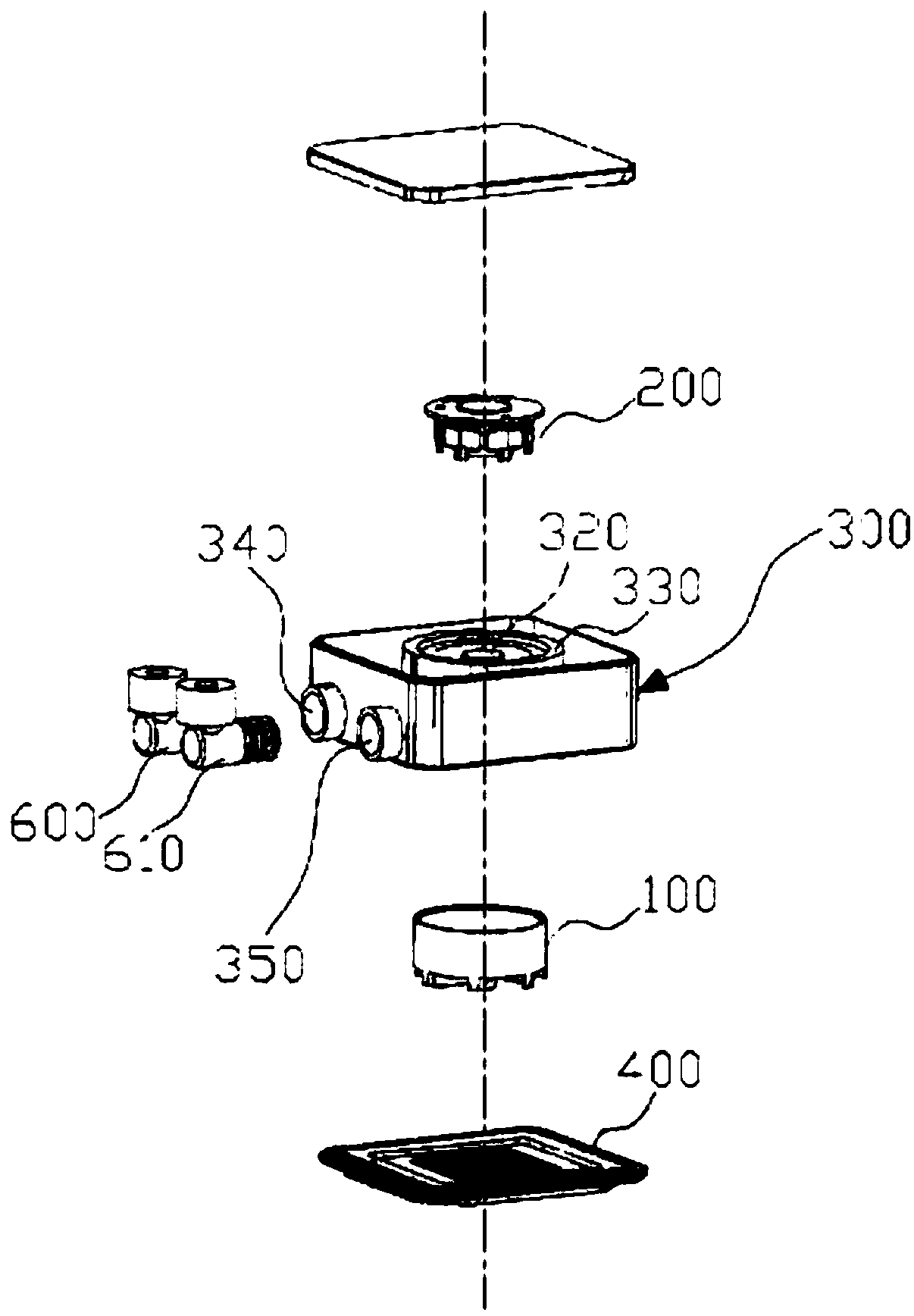
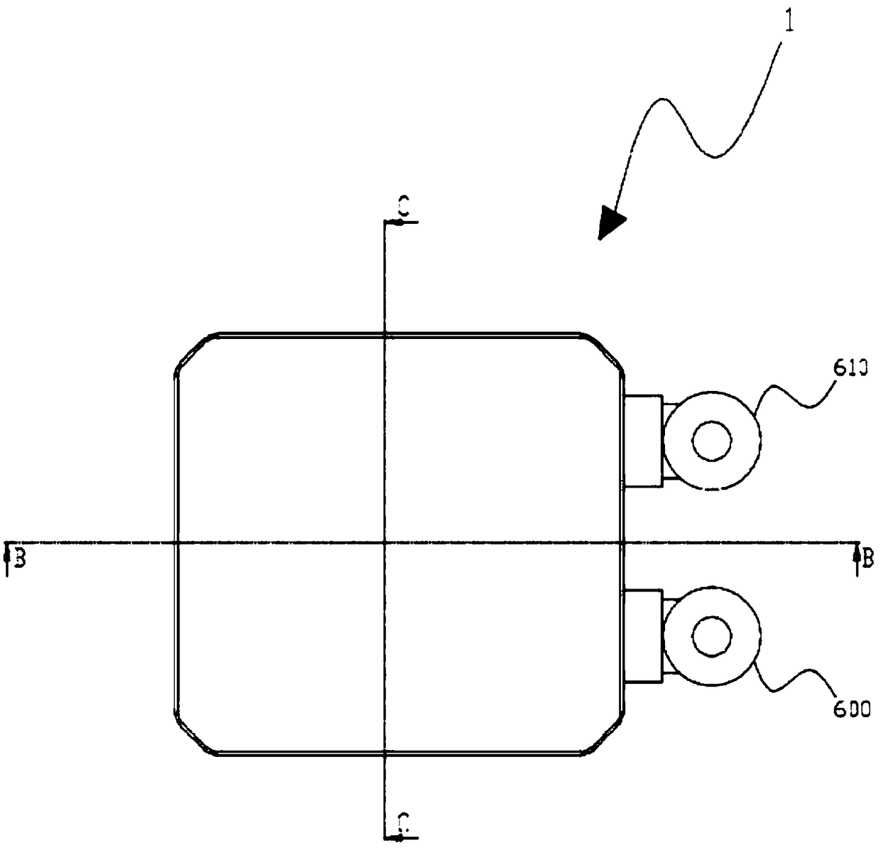
[0025] figure 1 is an exploded perspective view illustrating a structure of an electronic component cooling device according to an embodiment of the present invention, figure 2 It is a top view of the electronic component cooling device according to one embodime...


PUM


Abstract

According to an embodiment of the present invention, a gas / liquid pump can be configured through application of a two-phase cooling system, advantageously maximizing the cooling efficiency. To this end, particularly, an embodiment of the present invention may comprise an electronic part cooling device having a gas / liquid pump, comprising: an impeller positioned on a gas / liquid containing portion that contains a gas / liquid; a motor stator positioned on an outside isolated from the gas / liquid containing portion so as to transfer driving force to the impeller; a sealed injection cover having an impeller shaft formed on one side thereof so as to protrude toward the center of the gas / liquid containing portion such that the impeller is inserted therein, the sealed injection cover having a motorstator insertion rod formed on the other side thereof so as to protrude from an axis of the impeller shaft toward the center of the outside such that the motor stator is inserted therein, the sealed injection cover having an upper plate formed to expand from a periphery of the motor stator insertion rod such that the impeller and the motor stator are isolated from each other, and the sealed injection cover having an entrance and an exit formed on a side surface of the upper plate such that the gas / liquid flows in and out through the same, respectively; a heat transfer base thermally bonded orattached to the lower portion of the impeller along an edge of the upper plate such that the gas / liquid containing portion is formed; an inflow pipe thermally bonded or attached to the entrance such that the gas / liquid flows in through the same; an outflow pipe thermally bonded or attached to the exit such that the gas / liquid flows out through the same; and a condensing portion positioned betweenthe inflow pipe and the outflow pipe so as to condense the gas in the gas / liquid, wherein a vacuum is formed in an inner space defined by a close loop extending through the gas / liquid containing portion, the inflow pipe, the outflow pipe, and the condensing portion.

Description

technical field [0001] The present invention relates to an electronic component cooling device, and more specifically, to an electronic component cooling device equipped with a gas-liquid pump, which can efficiently cool electronic components by using the gas-liquid pump. Background technique [0002] The performance of electronic devices or electronic components such as processors is significantly affected by heat. The temperature range used to ensure optimum performance is very limited, so thermal management is an important part of managing the performance of these electronic components. [0003] At present, in order to improve the speed and performance of electronic components, various electronic component cooling devices have been developed, and mass production mainly uses air-cooled or water-cooled cooling devices. However, such an existing cooling device shows limited performance in terms of heat dissipation of electronic parts, so an electronic part cooling device ha...

Claims


Application Information

Patent Timeline
Patent Type & Authority Applications(China)
IPC IPC(8): H05K7/20H01L23/427F28D1/047
CPCH01L23/427F28D1/0477F28D2021/0031F28F2250/08F28D15/025F28D2021/0029F28D2015/0291F28D15/0266F28D1/047H05K7/20327H05K7/20336H05K7/20354F28D15/0241F28D15/06H05K7/20663
Inventor 尹国领
Owner ZALMAN TECH CO LTD
Why Eureka
Try Eureka