Combined cavity blow molding die

A technology of blow mold and combined cavity, which is applied in household appliances, other household appliances, household components, etc. It can solve problems affecting production efficiency and product quality, heat dissipation design, cavity cooling efficiency inconsistency, etc., to improve production Efficiency and product quality, improved consistency, and improved production flexibility

Pending Publication Date: 2018-12-25
HANGZHOU HESHENG PLASTIC PROD CO LTD
View PDF1 Cites 1 Cited by
  • Summary
  • Abstract
  • Description
  • Claims
  • Application Information

AI Technical Summary

Problems solved by technology

[0006] The multiple cavities in the prior art are of the same type, and due to the limitation of the mold bottom plate, the number of cavities is relatively fixed, and the heat dissipation design is not properly designed for different parts of the cavity, which leads to inconsistent cooling efficiency at different parts of the cavity. In turn, affect production efficiency and product quality

Method used


Image

  • Combined cavity blow molding die
  • Combined cavity blow molding die
  • Combined cavity blow molding die

Examples


Embodiment Construction

[0021] The present invention will be described in detail below in conjunction with the accompanying drawings.

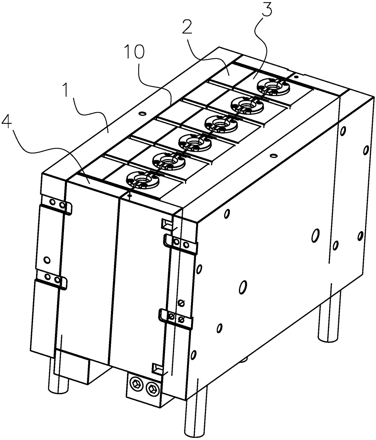
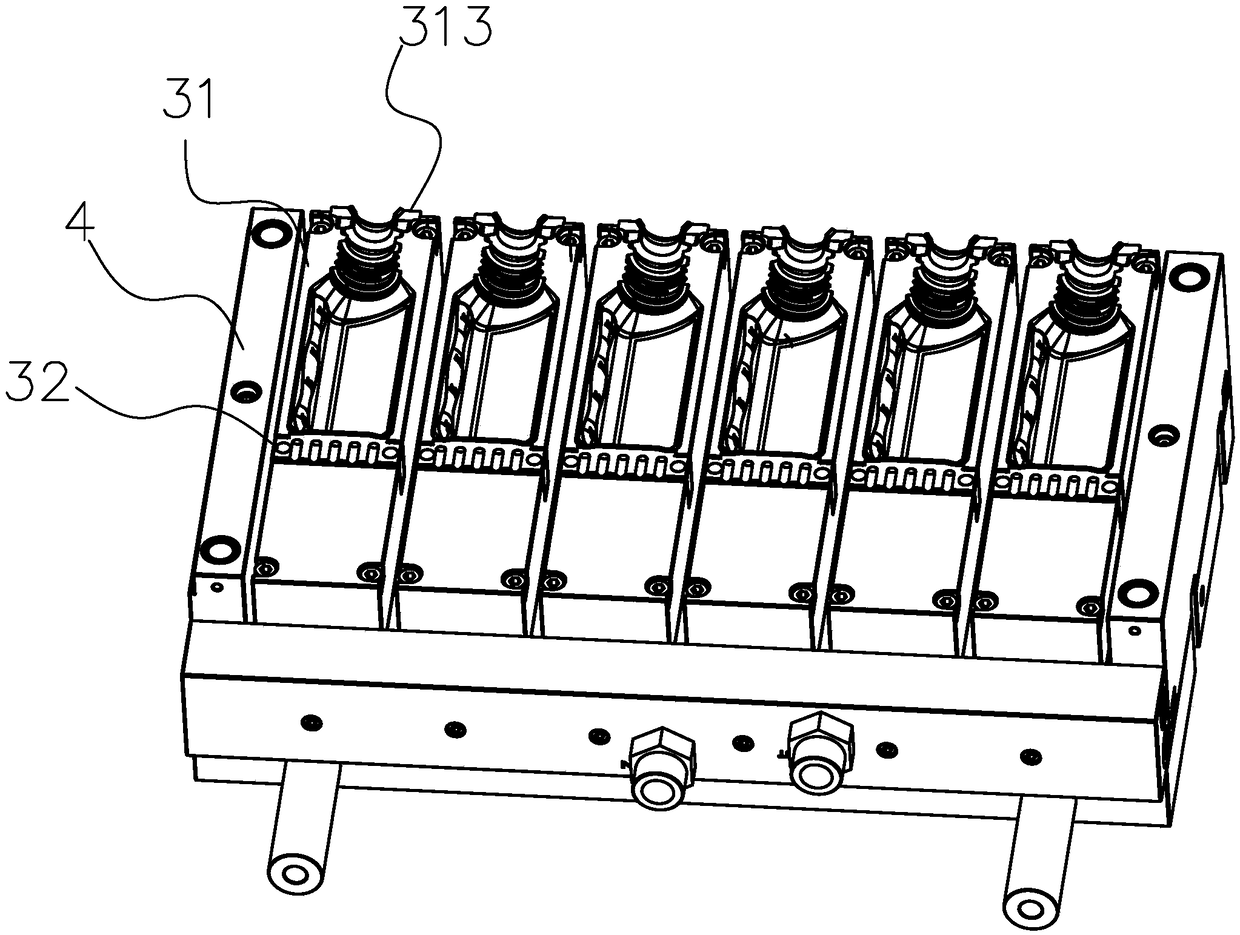
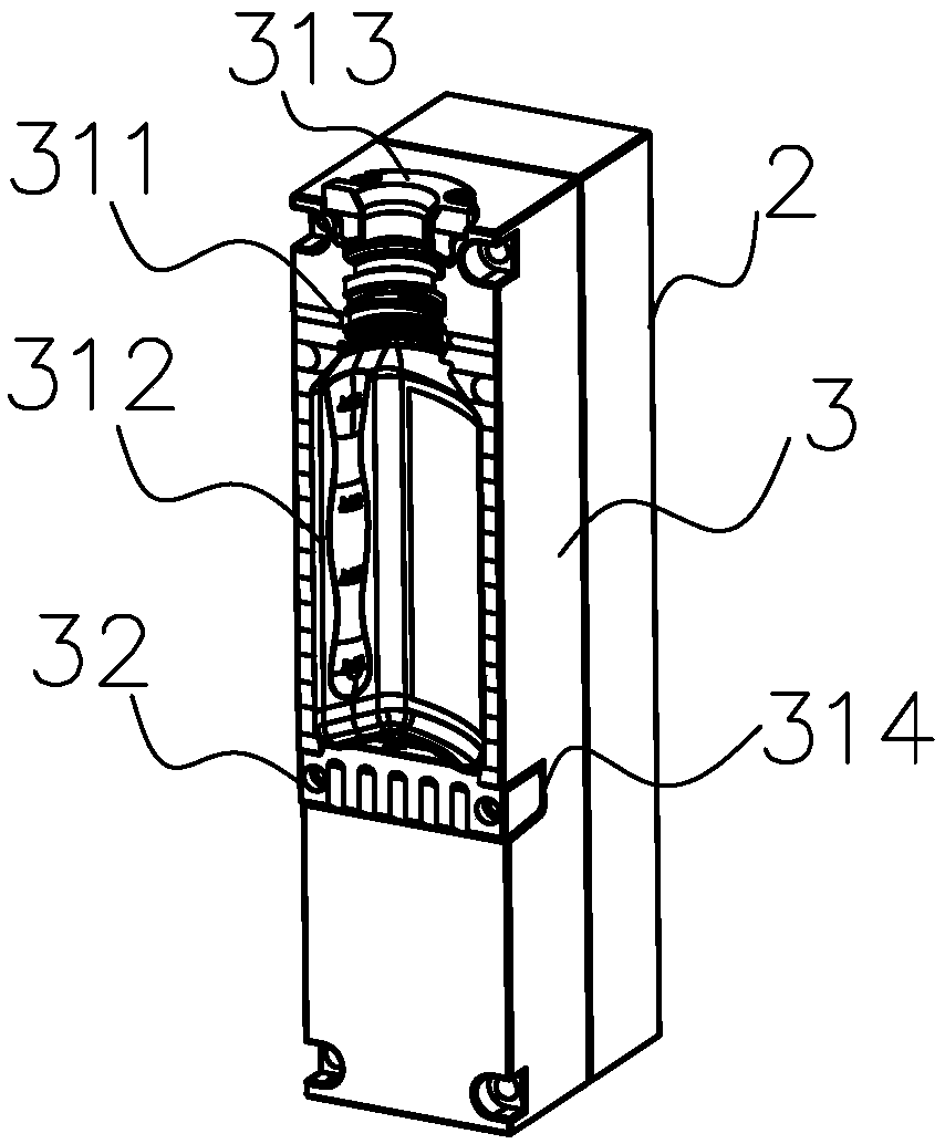
[0022] Such as figure 1 , figure 2 , image 3 and Figure 4 A combined cavity blow mold is shown, comprising: mutually independent cavity modules 3, mutually independent cooling modules 2, and a mold bottom plate 1; the cooling module 2 is installed on the mold bottom plate 1, and the The cavity module 3 is installed on the cooling module 2, and the cavity module 3, the cooling module 2, and the mold bottom plate 1 are all arranged in pairs. Due to the independent cavity module design, different numbers of cavity modules or even different types of cavity modules can be set according to production needs, which makes production more flexible, and the independent cooling modules reduce the number of cavity modules Does not affect cooling effect.

[0023] The cavity module 3 described in the present invention is a spliced ​​module including a bottle body cavity blo...


PUM


Abstract

The invention relates to the technical field of blow molding, in particular to a combined cavity blow molding die. The combined cavity blow molding die comprises mutually independent cavity modules, mutually independent cooling modules and die bottom plates. The cooling modules are mounted on the die bottom plates, the cavity modules are mounted on the cooling modules, and the cavity modules, thecooling modules and the die bottom plates are all disposed in pairs. The combined cavity blow molding die is provided with the mutually independent cavity modules, and has the advantages of flexible configuration, good cooling effect, good production efficiency and good product quality.

Description

technical field [0001] The invention relates to the technical field of blow molding, in particular to a combined cavity blow mold. technical background [0002] Existing plastic containers are usually produced by blow molding (or vacuum molding) using a hollow molding machine. The blow molding machine includes: a frame body, an extrusion device, a blow molding device, a mold device, a mold driving device and a cutting part. [0003] The mold device is movably arranged on the frame body, and has a first fixed position and a second fixed position on the frame body. The extrusion device is fixedly installed on the frame body, and is arranged on the upper side of the first fixed position of the mold device. The side of the output device close to the mold device is provided with a parison head for extruding a tubular parison. The blow molding device is fixedly installed on the frame body and arranged on the upper side of the second fixed position of the mold device. The blow mo...

Claims


Application Information

Patent Timeline
Patent Type & Authority Applications(China)
IPC IPC(8): B29C49/50B29C49/64B29L22/00
CPCB29C49/4823B29C49/50B29C49/64B29C2049/4825B29L2031/7158B29C49/4819
Inventor 游辉煜陈新红郑志义
Owner HANGZHOU HESHENG PLASTIC PROD CO LTD
Why Eureka
Try Eureka