
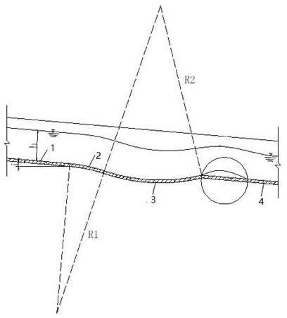
An aeration facility that uses water flow centripetal force and inertial deflection to form an aeration cavity

An inertial and centripetal force technology is applied in the field of aeration facilities that utilize the centrifugal force of water flow to form an aerated cavity. The effect of simple shape and convenient construction

Active Publication Date: 2020-09-08
SICHUAN UNIV
View PDF5 Cites 0 Cited by
  • Summary
  • Abstract
  • Description
  • Claims
  • Application Information

AI Technical Summary

Problems solved by technology

These special-shaped aeration sills solve the problem of aeration in individual projects, but the scope of application is limited, the shape is complex, and the construction is difficult

Method used


Image

  • An aeration facility that uses water flow centripetal force and inertial deflection to form an aeration cavity
  • An aeration facility that uses water flow centripetal force and inertial deflection to form an aeration cavity
  • An aeration facility that uses water flow centripetal force and inertial deflection to form an aeration cavity

Examples


Embodiment

[0028] A hydropower station hub consists of a main dam, discharge structures, and a factory building behind the dam. The barrage dam is a roller compacted concrete gravity dam, and the flood discharge structure is arranged on the riverbed dam section, consisting of five surface holes and two bottom holes. Two bottom hole spillway are arranged on both sides of the surface hole spillway. The bottom slope of the flood discharge tunnel is 3%. The original aeration and corrosion reduction uses the existing form of a combination of ridges and grooves. After operation, cavitation damage to the bottom of the flood discharge tunnel and large-area return water to the aeration cavity occurred. In the restoration project, the original aeration and corrosion reduction facilities were removed, and an aeration facility was used to form an aeration cavity by utilizing the centripetal force inertial deflection of water flow.

[0029] The specific structure is as Figure 1-4 As shown, the aera...


PUM


Abstract

The invention provides an aeration facility for forming an aerated cavity by using a water flow centripetal force inertia deflecting flow. The aerated cavity is formed by using inertance of concave curve section water flow centripetal force to guide and control the deflecting of water flow. The aeration facility is arranged on the upstream of a position at which cavitation of the water flow of a release structure may occur, includes an overflowing bottom plate and a side wall and is composed of an upstream straight section, a convex curve section, a concave curve section and a downstream straight section which are sequentially connected in the water flow direction. The upstream straight section and the downstream straight section are correspondingly connected to an upstream bottom plate and a downstream bottom plate of the release structure, and a bottom plate of the convex curve section is in an arc shape protruding inwardly to a water body and is tangentially connected with bottom plates of the upstream straight section and the concave curve section so that the water flow can smoothly transit from the upstream straight section into the concave curve section; the bottom plate of the concave curve section is in a downwardly concave arc shape and is connected with the bottom plate of the downstream straight section in a linear-tangential mode. The aeration facility has a simplestructure and a good aeration effect, and is particularly suitable for aeration and erosion reduction of a release structure with a high flow rate and a small bottom slope.

Description

technical field [0001] The invention belongs to the technical field of aeration and corrosion reduction for high-velocity water flow of discharge structures in water conservancy and hydropower projects, and in particular relates to an aeration facility. Background technique [0002] In recent years, with the vigorous development of water conservancy and hydropower in my country, the number of high dams has continued to increase. Some special water flow phenomena, such as cavitation and cavitation, will occur in the discharge structures of these projects due to the high flow velocity. Cavitation damages the flow surface of the drainage structure; affects the water flow shape and reduces the flow capacity; in severe cases, it will also affect the normal use of the drainage structure and shorten the service life of the drainage structure. Therefore, preventing cavitation damage is very important for the normal operation of high-velocity drainage structures. [0003] When the w...

Claims


Application Information

Patent Timeline
Patent Type & Authority Patents(China)
IPC IPC(8): E02B8/06
CPCE02B8/06
Inventor 张法星王红艳刘善均邓军田忠许唯临王韦周茂林
Owner SICHUAN UNIV
Learn More