
anti-skid device

A technology of anti-skid device and gear, applied in the direction of building, building reinforcements, building components, etc., can solve the problems of inability to grip steel strands and weak tensile strength.

Active Publication Date: 2021-04-27
浙锚科技股份有限公司
View PDF5 Cites 0 Cited by
  • Summary
  • Abstract
  • Description
  • Claims
  • Application Information

AI Technical Summary

Problems solved by technology

[0005] The object of the present invention is to provide an anti-slip device, which solves the problem that the existing steel strand load-bearing equipment near the fixed column in the middle of the steel strand cannot bite the steel strand with an epoxy resin layer, and the gap between it and the steel strand is easy. Relative sliding occurs, which leads to the defect of weak tensile strength

Method used


Image

  • anti-skid device
  • anti-skid device

Examples


Embodiment 1

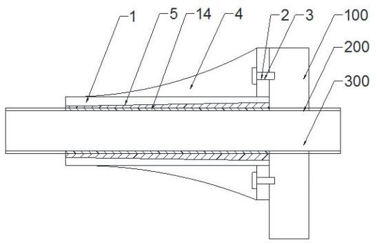
[0029] Such as figure 1 , figure 2 As shown, a kind of anti-slip device provided by the present invention is used to cover on the steel strand 300 with epoxy resin outer layer 200 near one end of the fixed column 100; comprising: force component sleeve 1; the proximity of the force component sleeve One end of the fixed column has a contact base 2; the contact base is fixed on the fixed column by a fastener 3. There are a plurality of reinforcing ribs 4 on one side of the contact base, and the width of the reinforcing ribs converges from one end adjacent to the fixing column to the other end.

[0030] The inner diameter of the force component sleeve converges from one end close to the fixed column to the other end away from the fixed column, forming an inclined inner tapered surface 5 . The inner wall of the force component sleeve is provided with multiple sets of ring gears; the ring gears include a first gear 6, a second gear 7 and a third gear 8, the first gear, the secon...

Embodiment 2

[0035] An anti-skid device provided by the present invention is used to cover a steel strand with an outer layer of epoxy resin near one end of a fixed column; comprising: a force component sleeve; the inner wall of the force component sleeve is provided with multiple groups of ring gears ; The ring gear has inner hard teeth and outer soft teeth covering the outer surface of the inner hard teeth, the hardness of the inner hard teeth is less than the hardness of the steel strand, and the hardness of the outer soft teeth is less than the inner hard teeth hardness; on the axial section, the inner hard tooth is a convex peak with a rounded curve, and the outer side of the outer soft tooth has a pair of protruding heads bifurcated to both ends; when installed, the protruding After the head squeezes into the epoxy resin layer of the steel strand, it touches the steel strand and bends and deforms to form an anti-skid layer.


PUM


Abstract

An anti-skid device provided by the present invention is used to cover a steel strand with an outer layer of epoxy resin near one end of a fixed column; comprising: a force component sleeve; the inner wall of the force component sleeve is provided with multiple groups of ring gears ; The ring gear has inner hard teeth and outer soft teeth covering the outer surface of the inner hard teeth, the hardness of the inner hard teeth is less than the hardness of the steel strand, and the hardness of the outer soft teeth is less than the inner hard teeth hardness; on the axial section, the inner hard tooth is a convex peak with a rounded curve, and the outer side of the outer soft tooth has a pair of protruding heads bifurcated to both ends; when installed, the protruding After the head squeezes into the epoxy resin layer of the steel strand, it touches the steel strand and bends and deforms to form an anti-skid layer. The present invention sets inner hard teeth and outer soft teeth and configures convex heads, which greatly increases the clamping force between the steel strands with epoxy resin layer, and avoids the relative sliding between the anti-slip device and the steel strands, while resulting in weak tensile strength.

Description

technical field [0001] The invention relates to the field of steel strand fastening equipment, in particular to an anti-slip device. Background technique [0002] When the existing steel strands are used, the tensile force on one end is usually smaller than that on the other end. In order to balance the force on the steel strands, it is necessary to add a force component device fixed on the fixed column; the existing steel strands use a The fixed anchor lacks a device for component fastening in the middle of the steel strand, and cannot bite the steel strand with an epoxy resin layer, and it is easy to generate relative sliding between it and the steel strand, resulting in weak tensile capacity . [0003] The existing patent document with the application number CN201721322043.7 discloses the patent document "A Prestressed Steel Strand Connection Device". The force device cannot bite the steel strand with epoxy resin layer, and it is easy to generate relative sliding betwee...

Claims


Application Information

Patent Timeline
Patent Type & Authority Patents(China)
IPC IPC(8): E04C5/12
CPCE04C5/12
Inventor 周成顺曾利宋强
Owner 浙锚科技股份有限公司
Learn More