
Swing-type gap grouting device for building

A swinging, construction-use technology, applied in construction, building maintenance, building construction, etc., can solve the problems of nozzle damage and short service life of the nozzle, and achieve the effect of increasing the grouting flow, improving the service life and uniform grouting

Active Publication Date: 2018-12-25
HUNAN CITY UNIV
View PDF10 Cites 4 Cited by
  • Summary
  • Abstract
  • Description
  • Claims
  • Application Information

AI Technical Summary

Problems solved by technology

[0004] In the gap grouting device for construction in the above cited documents, during the swinging process of the nozzle, the movement of the nozzle drives the slider to slide in the sliding clamping cavity to realize the telescopic swing grouting of the nozzle; however, due to the motion of the nozzle, the slider is driven to Sliding and clamping Sliding in the cavity can only be achieved after the nozzle and the inner wall of the gap are squeezed. During the grouting process of the nozzle, if the nozzle and the inner wall of the gap are kept in contact for a long time, the nozzle will be damaged easily, and the service life of the nozzle is short.

Method used


Image

  • Swing-type gap grouting device for building
  • Swing-type gap grouting device for building
  • Swing-type gap grouting device for building

Examples


Embodiment

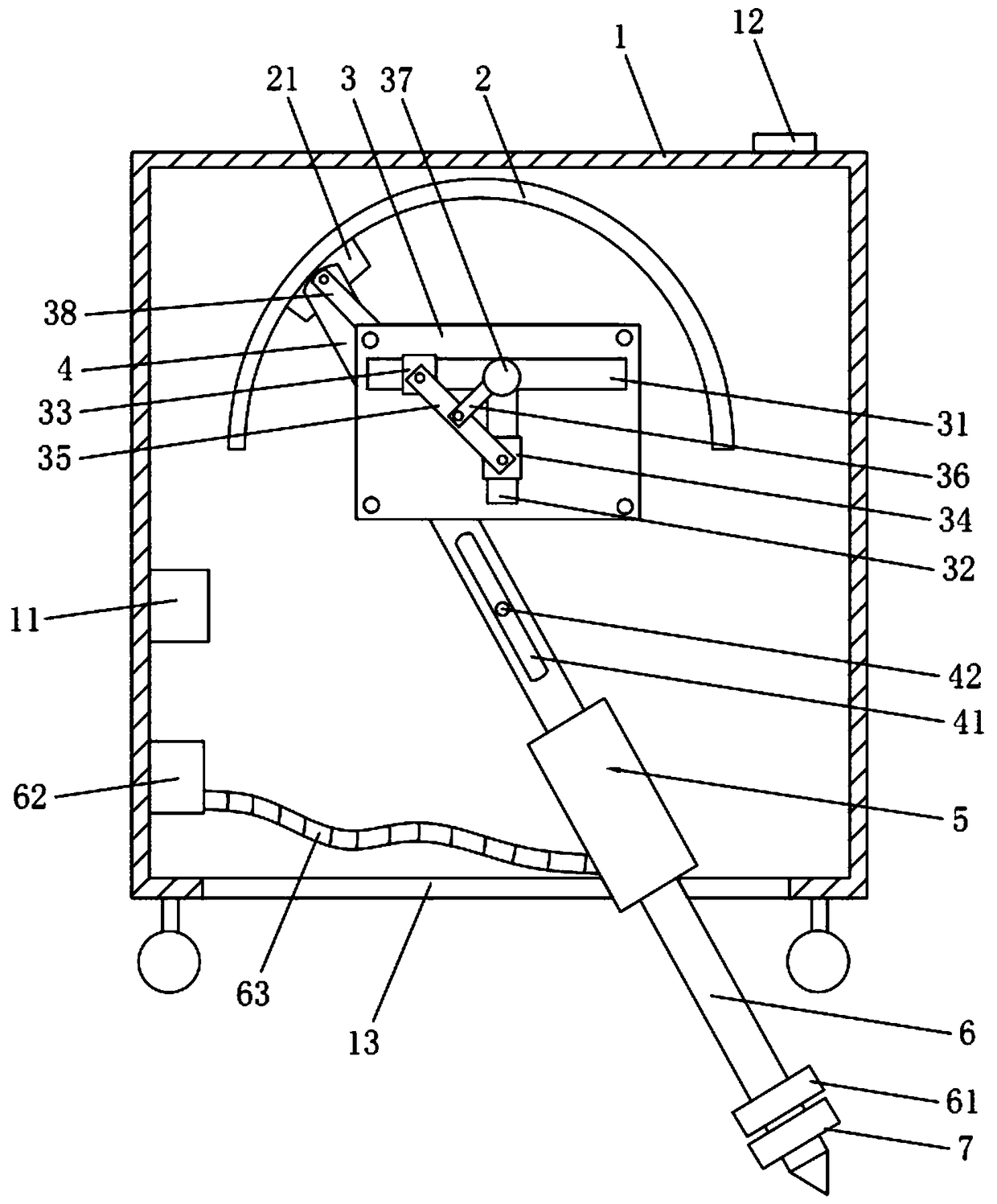
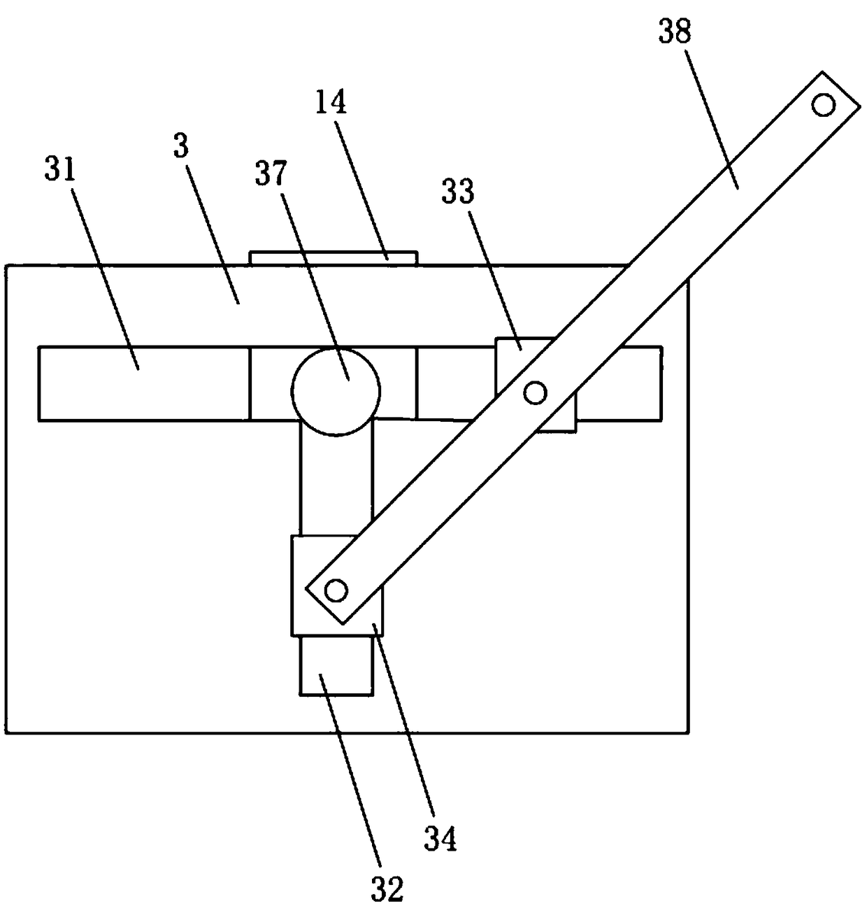
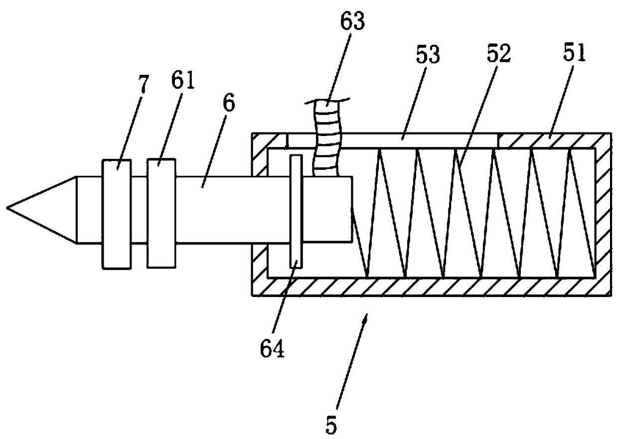
[0024] Embodiment: a kind of swinging type gap grouting device for construction, such as figure 1 As shown, it includes a main box body 1, a semi-elliptical slide rail 2 fixedly connected with the inner wall of the main box body 1, a slider 21 slidingly connected with the semi-elliptical slide rail 2, a swing rod 4, a spray head 6 and a 21 drive assemblies that move along the arc track direction of the semi-elliptical slide rail 2. The arc track of the semi-elliptical slide rail 2 in this embodiment is an arc curve intercepted along the short axis direction of the ellipse track. One end of the swing rod 4 is rotatably connected with the slider 21 , and the other end is fixedly connected with the spray head 6 . The inner wall of the main box body 1 is fixedly connected with a fixed shaft 42 , and the swing rod 4 is provided with a sliding groove 41 for inserting the fixed shaft 42 , and the sliding groove 41 extends along the length direction of the swing rod 4 . A hydraulic ...


PUM


Abstract

The invention discloses a swing-type gap grouting device for a building and relates to the technical field of building equipment. The problem is solved that in the grouting process of a spray nozzle,the spray nozzle and the inner wall of a gap are in contact for a long time, and accordingly the spray nozzle is easily damaged. The swing-type gap grouting device is characterized by comprising a main box, a semi-elliptical slide rail fixedly connected with the inner wall of the main box, a slide block slidingly connected with the semi-elliptical slide rail, a swing rod, a spray nozzle and a driving assembly for driving the slide block to move in the arc track direction of the semi-elliptical slide rail; one end of the swing rod is rotatably connected with the slide block, and the other end of the swing rod is fixedly connected with the spray nozzle; a fixing shaft is fixedly connected to the inner wall of the main box, and a slide groove for the fixing shaft to be inserted in is formed in the swing rod; a hydraulic pump is fixedly connected to the inner wall of the main box, a conveying pipe is arranged between the hydraulic pump and the spray nozzle, and a swing groove for the spraynozzle to swing in runs through the bottom of the main box. The swing-type gap grouting device has the advantages that the spray nozzle does not abut against the inner wall of the gap in the groutingprocess, and the service life of the spray nozzle is prolonged.

Description

technical field [0001] The invention relates to the technical field of construction equipment, more specifically, it relates to a swing type gap grouting device for construction. Background technique [0002] The grouting machine is a professional construction tool for chemical grouting plugging and structural reinforcement of cracks, expansion joints, construction joints, and structural joints in various buildings and underground concrete woodwork. [0003] A Chinese patent with the announcement number CN105971301A and the announcement date of September 28, 2016 has been retrieved, which discloses a construction gap grouting device, including a base frame and a rear wall connected to the base frame through a rotating support device. A connected nozzle connection device, wherein the nozzle connection device includes a nozzle rotation driving housing with a sliding clamping cavity, and a nozzle movement driving slider is slidably fitted in the sliding clamping cavity. [000...

Claims


Application Information

Patent Timeline
Patent Type & Authority Applications(China)
IPC IPC(8): E04G23/02
CPCE04G23/0211
Inventor 彭朝晖陈锶刘益虹孟茁超陈利群谢金
Owner HUNAN CITY UNIV
Learn More