
Speed ​​synchronizer for gearbox

A speed synchronization and gearbox technology, applied in clutches, mechanical drive clutches, mechanical equipment, etc., can solve the problems of complex structure, high cost, and unsuitable simple speed change requirements of synchronizers, and achieve convenient operation, fast response, and simple structure. Effect

Active Publication Date: 2020-05-05
JIANGSU UNIV
View PDF12 Cites 0 Cited by
  • Summary
  • Abstract
  • Description
  • Claims
  • Application Information

AI Technical Summary

Problems solved by technology

[0004] Synchronizers currently on the market have complex structures and high costs, and are not suitable for occasions that require simple speed change

Method used


Image

  • Speed ​​synchronizer for gearbox
  • Speed ​​synchronizer for gearbox
  • Speed ​​synchronizer for gearbox

Examples


Embodiment Construction

[0032] The present invention will be further described below with reference to the drawings and specific embodiments, but the protection scope of the present invention is not limited to this.

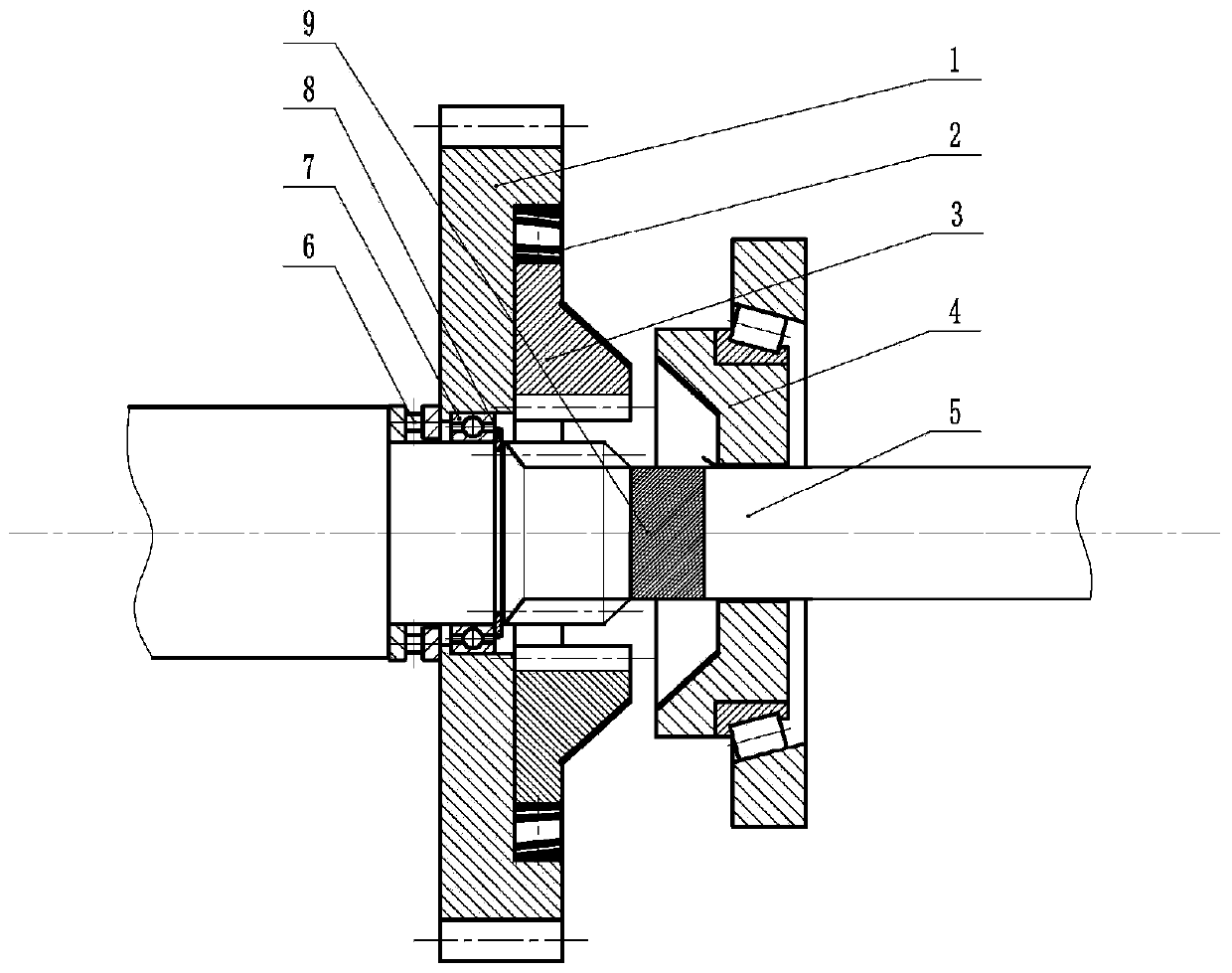
[0033] Such as figure 1 As shown, the speed synchronizer for a gearbox of the present invention includes a slider 3 and a synchronizing ring 4; a gear 1 meshes with the gear train of the gearbox, the gear 1 is mounted on the shaft 5 through a bearing, and the gear 1 A radially sliding slider 3 is provided on the upper part. The synchronizer ring 4 is mounted on the shaft 5, and the synchronizer ring 4 is moved axially through the shift fork; when the synchronizer ring 4 contacts the slider 3, the radially moves The sliding block 3 is in transmission connection with the shaft 5 for synchronous rotation of the gear 1 and the shaft 5.

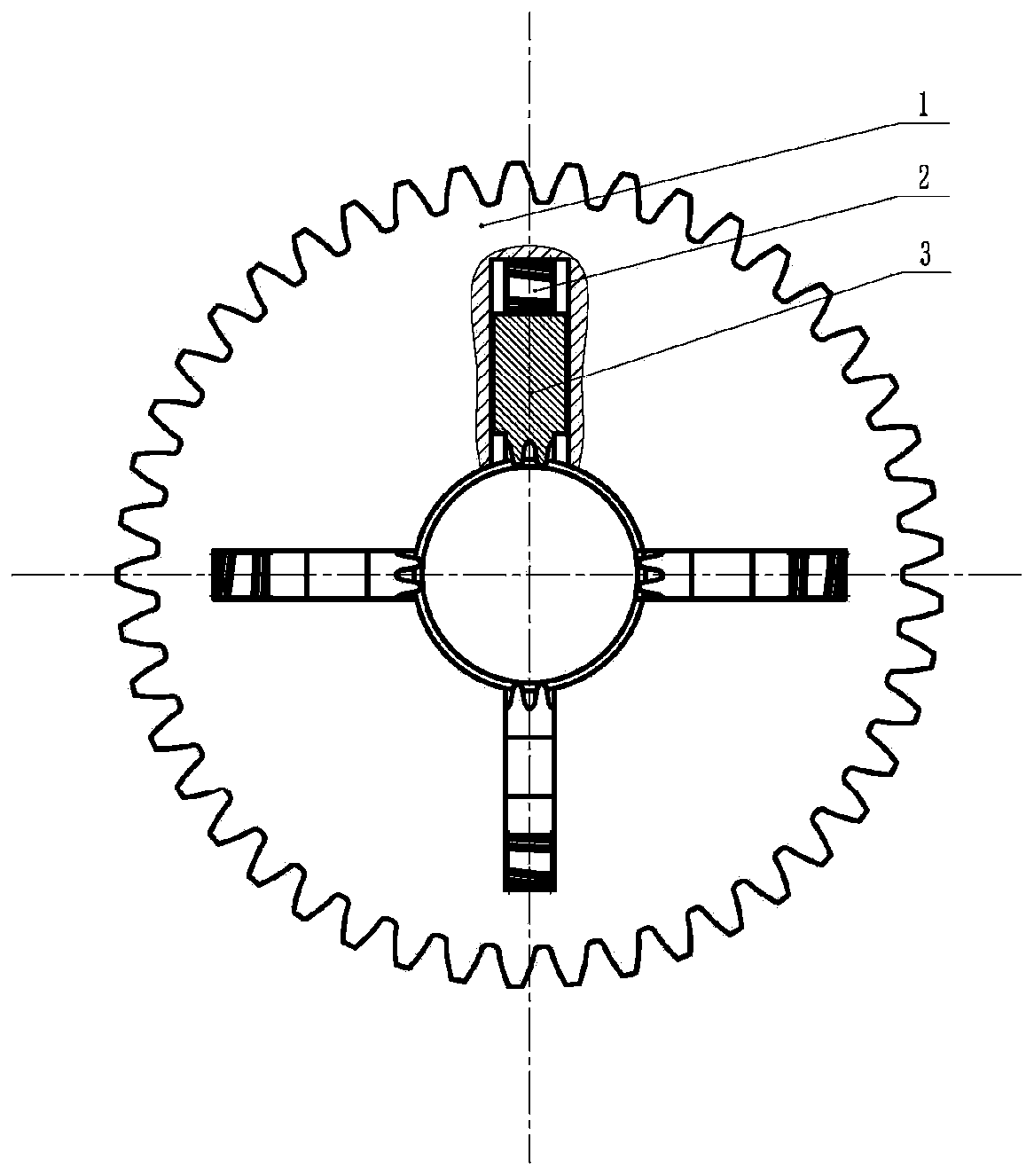
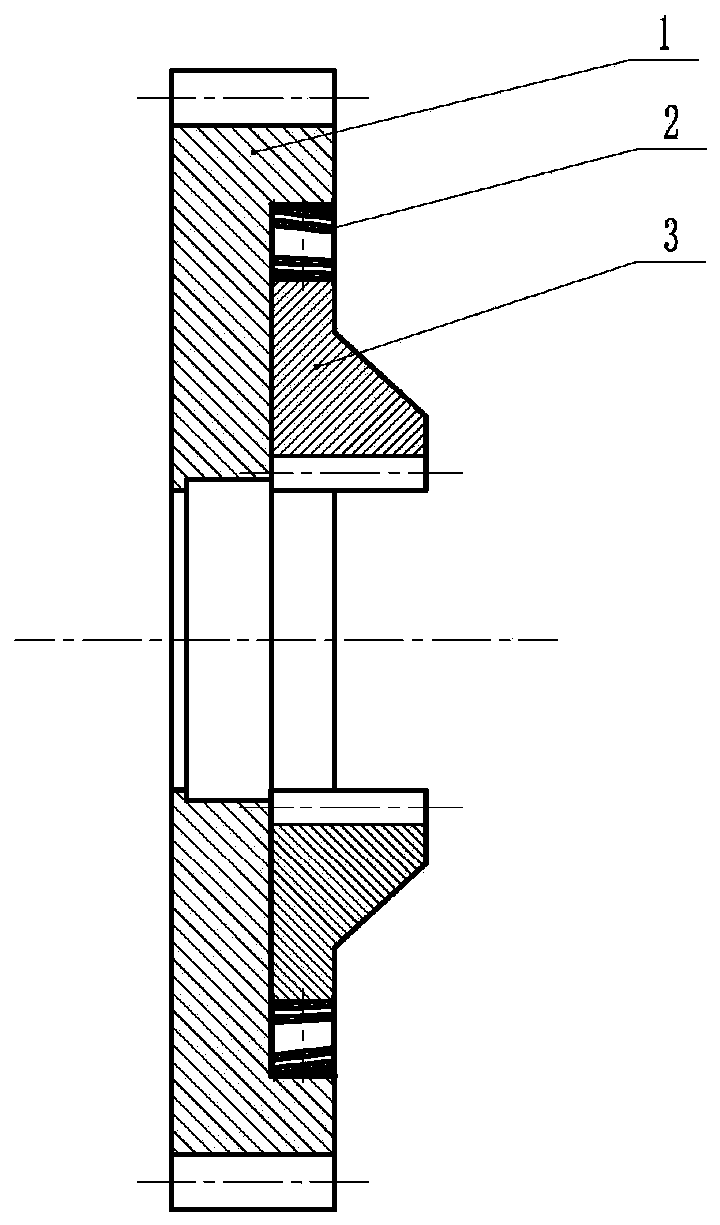
[0034] Such as figure 1 And as figure 2 As shown, the end surface of the gear 1 is provided with 4 convex grooves for mounting the slider 3, and the hub of the...


PUM


Abstract

The invention provides a rotating speed synchronizer for a transmission. The rotating speed synchronizer comprises sliding blocks and a synchronous ring. A gear is engaged with a gear train of the transmission and is mounted on a shaft through a bearing. The sliding blocks sliding in the radial direction are arranged on the gear, the synchronous ring is mounted on the shaft, and the synchronous ring moves in the axial direction through a shifting fork. When the synchronous ring is in contact with the sliding blocks, the sliding blocks sliding in the radial direction are in transmission connection with the shaft to be used for enabling the gear and the shaft to rotate synchronously. Multiple evenly-distributed grooves are arranged on the end face of the gear, and the corresponding sliding block sliding in the radial direction is placed in each groove. The rotating speed synchronizer further comprises a reset spring device, one end of the reset spring device is connected with the slidingblocks, and the other end of the reset spring device is connected with the grooves. The rotating speed synchronizer is simple in structure, fast in response, convenient to operate and suitable for various manual and automatic transmissions.

Description

Technical field [0001] The invention relates to the technical field of synchronizers, in particular to a speed synchronizer for gearboxes. Background technique [0002] There is a very important device inside the structure of the gearbox, which is the "synchronizer". The function of the synchronizer is very obvious, that is, when the gear is shifted, the speed of the power output gear is faster than the gear that is about to be changed into this gear. If there is no synchronizer, a slow-rotating gear is forced into a high-speed gear. In the rotating gear, the phenomenon of tooth punching will definitely occur. The synchronizer can not only ensure normal gear shifting, but also play a buffering role. The number and material of the conical friction plate set directly affect the performance of the synchronizer. [0003] Synchronizers are available in normal pressure, inertial, and self-increasing forms. The inertial synchronizer is widely used at present. It is mainly composed of ...

Claims


Application Information

Patent Timeline
Patent Type & Authority Patents(China)
IPC IPC(8): F16D23/04
CPCF16D23/04
Inventor 朱荣生陈靖王秀礼陈一鸣安策
Owner JIANGSU UNIV
Learn More