Multistage condensation miniature hot water stove

A technology for condensing and hot water stoves, which is applied in the field of gas stoves, can solve the problems of increasing investment costs and management production costs of enterprises, reducing thermal efficiency of boilers, and being unsuitable, so as to improve heat exchange efficiency, improve thermal efficiency, and avoid safety. hidden effect

Pending Publication Date: 2018-12-25
南充烽英堂厨房电器设备科技有限公司
View PDF0 Cites 1 Cited by
  • Summary
  • Abstract
  • Description
  • Claims
  • Application Information

AI Technical Summary

Problems solved by technology

[0002] At present, gas-fired boilers are commonly used in the market to produce hot water, which occupy a large area, require large investment, and are inconvenient to manage.
When the boiler produces hot water, its high-temperature exhaust gas takes away part of the heat, resulting in a decrease in the thermal efficiency of the boiler, and it is not very suitable for small collectives and small groups to use boilers for hot water production, which increases the investment cost and management production cost of the enterprise

Method used


Image

  • Multistage condensation miniature hot water stove
  • Multistage condensation miniature hot water stove

Examples


Embodiment 1

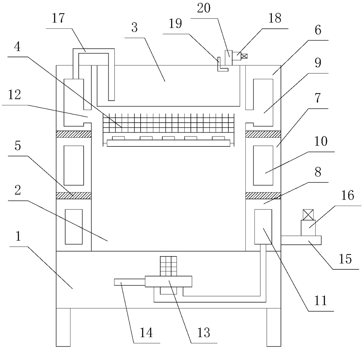
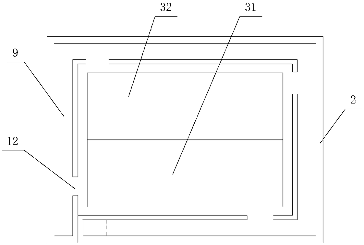
[0027] Such as figure 1 and figure 2 As shown, the multi-stage condensing miniature hot water stove provided in this embodiment includes a stove body 1 and a combustion chamber 2, and a heating water tank 3 is installed on the upper part of the stove body 1, and the heating water tank 3 includes a medium-temperature water tank 31 and a high-temperature water tank 32. The medium-temperature water tank 31 and the high-temperature water tank 32 are identical and arranged side by side. A heating fire row 4 is installed in the combustion chamber 2. The heating fire row 4 is located directly below the medium-temperature water tank 31 and the high-temperature water tank 32. The medium-temperature water The box 31 and the high-temperature water tank 32 are subjected to different combustion heat by the heated fire row 4. There is a cavity around the outer wall of the combustion chamber 2 in the said stove body 1, and two annular horizontal partitions are arranged in the cavity from to...

Embodiment 2

[0030] This embodiment is basically the same as Embodiment 1, except that the high-temperature tail gas heat exchange channel 9, the medium-temperature tail gas heat-exchange channel 10 and the low-temperature tail gas heat-exchange channel 11 have been changed. The cross-sections of the channel 10 and the low-temperature exhaust gas heat exchange channel 11 are rectangular; the cross-sectional areas of the high-temperature exhaust gas heat exchange channel 9, the medium-temperature exhaust gas heat exchange channel 10, and the low-temperature exhaust gas heat exchange channel 11 decrease successively, and their wall thickness Also decrease in turn; the high temperature tail gas heat exchange channel 9 is made of stainless steel, the medium temperature tail gas heat exchange channel 10 and the low temperature tail gas heat exchange channel 11 are made of copper or aluminum.

[0031]Working principle: when the hot water stove starts to work, the heating fire row 4 is started, an...


PUM


Abstract

The invention discloses a multistage condensation miniature hot water stove, comprising a stove body and a combustor. A heating tank is mounted in the upper portion of the stove body; a heating grateis mounted in the combustor; the inside of the stove body is divided by two horizontal partitions which are circular into a primary waste heat exchange area, a secondary waste heat exchange area and atertiary waste heat exchange area sequentially from top to bottom; a plurality of high-temperature tail gas inlets communicated with the combustor are arranged evenly in the primary waste heat exchange area in spaced manner; an intensive exhaust fan is externally connected to the tertiary waste heat exchange area and is connected with a tail gas discharge pipe; a water incoming pipe is also connected with the tertiary waste heat exchange area; a hot water outgoing pipe is connected to the top of one side of the primary waste heat exchange area; a water outlet of the hot water outgoing pipe ispositioned in the heating tank. The multistage condensation miniature hot water stove has the advantages that high-temperature tail gas generated by the combustor is subjected to efficient heat exchanging, hot water produced by heat exchanging is delivered into the heating tank, energy consumption for heating is reduced, and application cost is reduced.

Description

technical field [0001] The invention belongs to the field of gas stoves, and in particular relates to a multi-stage condensing miniature hot water stove. Background technique [0002] At present, gas-fired boilers are generally used in the market to produce hot water, which occupy a large area, require a large investment, and are inconvenient to manage. When the boiler produces hot water, its high-temperature exhaust gas takes away part of the heat, resulting in a decrease in the thermal efficiency of the boiler, and it is not very suitable for small collectives and small groups to use boilers for hot water production, which increases the investment cost and management production cost of the enterprise . Contents of the invention [0003] The technical problem to be solved by the present invention is to provide a multi-stage condensing miniature hot water stove, which can effectively improve thermal efficiency and reduce investment, management and production costs compare...

Claims


Application Information

Patent Timeline
Patent Type & Authority Applications(China)
IPC IPC(8): F24C13/00F24H8/00F24H9/20
CPCF24C13/00F24H8/00F24H9/2007Y02B30/00
Inventor 王尚兵
Owner 南充烽英堂厨房电器设备科技有限公司
Why Eureka
Try Eureka