Dust removal equipment for melting furnace

A technology for dust removal equipment and furnaces, applied in lighting and heating equipment, furnaces, charge materials, etc., can solve the problems of wasting energy, polluting the environment, and insufficient recycling of steel slag, and achieve the effect of avoiding safety accidents and preventing sparks from being ejected.

Inactive Publication Date: 2018-12-25
四川凯隆轩工程材料有限公司
View PDF0 Cites 2 Cited by
  • Summary
  • Abstract
  • Description
  • Claims
  • Application Information

AI Technical Summary

Problems solved by technology

[0003] The existing steel scrap is recycled and smelted and directly discharged into the atmosphere. T

Method used


Image

  • Dust removal equipment for melting furnace
  • Dust removal equipment for melting furnace

Examples


Embodiment Construction

[0020] The present invention will be described in further detail below through specific implementation examples and in conjunction with the accompanying drawings.

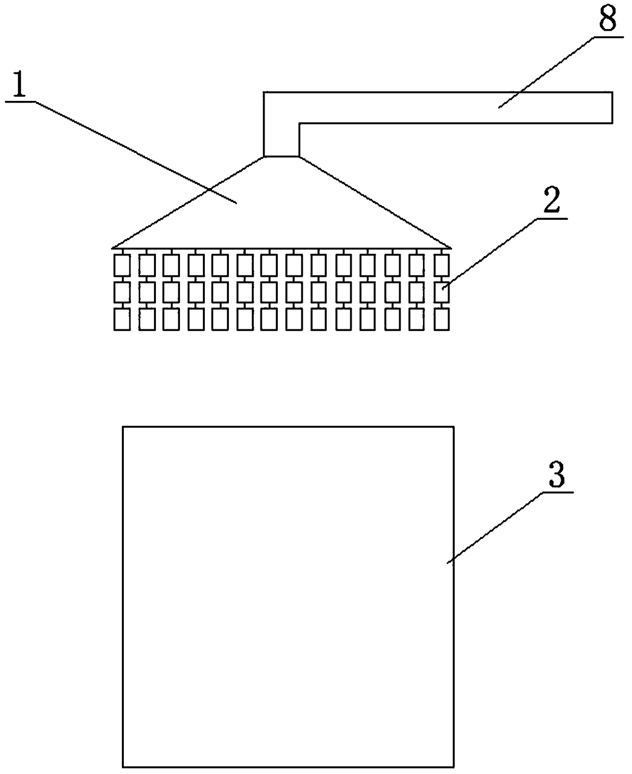
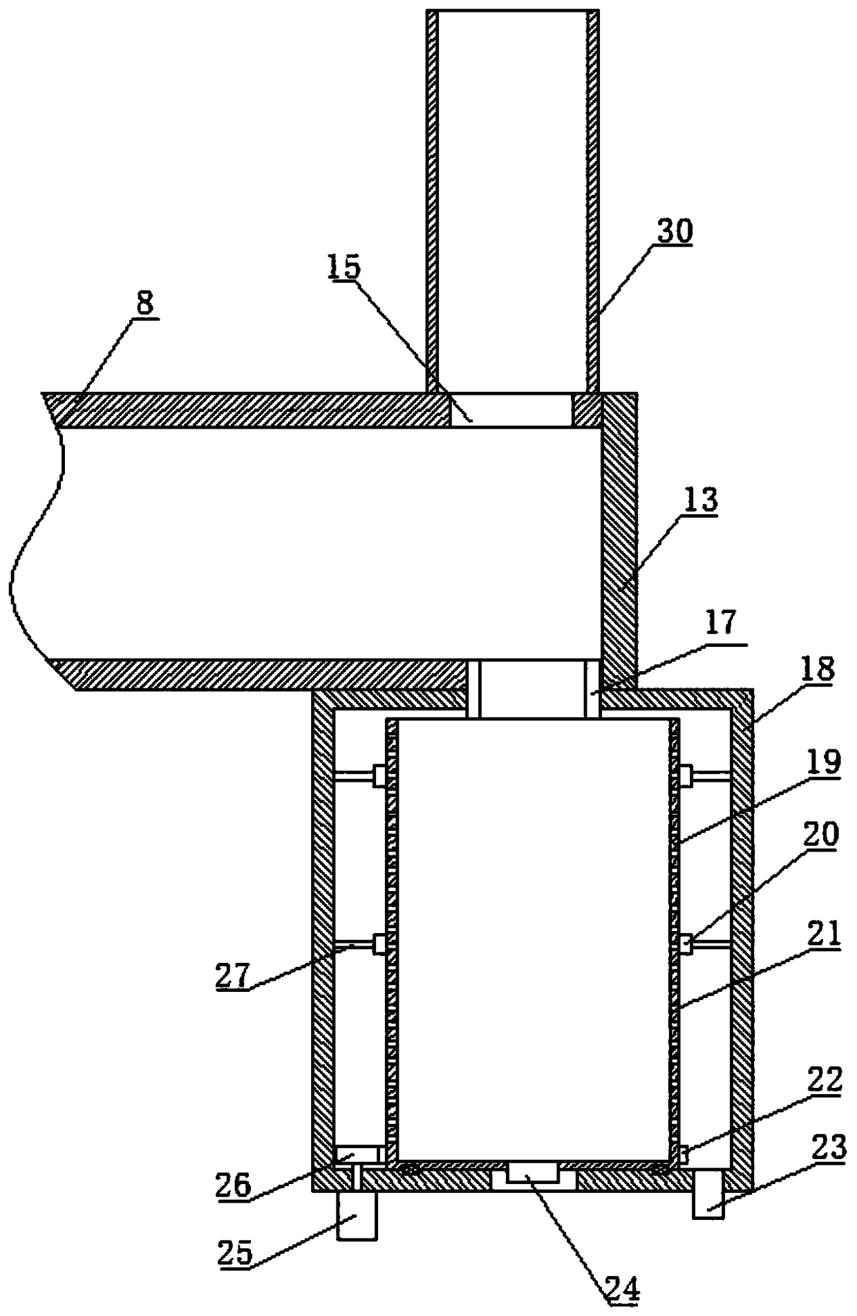
[0021] Figure 1-2 It shows a kind of furnace dust removal equipment provided by the present invention, which includes a dust removal cover body 1, and a plurality of baffle plate groups 2 are arranged on the lower end of the dust removal cover body 1, and each baffle plate group 2 includes a top-to-bottom A plurality of baffles arranged at intervals, and two adjacent baffles are connected by iron chains; the upper end of the dust removal hood body 1 is provided with a transverse flue 8, and the smoke outlet end of the transverse flue 8 is provided with a cover plate 13, The upper end of the horizontal flue 8 is provided with a smoke outlet 15, and the lower end is provided with a slag outlet; the smoke outlet 15 is arranged correspondingly to the upper and lower sides of the slag outlet; the horizontal flue 8 is p...


PUM


Abstract

The invention discloses dust removal equipment for a melting furnace. The dust removal equipment comprises a dust removal cover body. A plurality of baffle groups are arranged in rows on the circularsurface of the lower end of the dust removal cover body. Each baffle group comprises a plurality of baffles arranged at intervals from top to bottom, and every two adjacent baffles are connected through an iron chain. A transverse flue is arranged at the upper end of the dust removal cover body. A cover plate is arranged at the smoke outlet end of the transverse flue. A smoke outlet is formed in the upper end of the transverse flue, and a slag outlet is formed in the lower end of the transverse flue. The slag outlet of the transverse flue is communicated with the interior of a separation cylinder through a pipeline. A vertical smoke exhaust channel is fixedly arranged in the position, at the smoke outlet, of the transverse flue. The dust removal equipment is beneficial to application and popularization.

Description

technical field [0001] The invention relates to the technical field of dust removal hood treatment, in particular to a furnace dust removal equipment. Background technique [0002] Furnace dust removal equipment is a necessary equipment for steelmaking plants, and its function is mainly to discharge the waste gas generated by the furnace during steelmaking and ironmaking. [0003] Existing scrap steel is directly discharged into the atmosphere during recycling and smelting. The steel slag in the flue gas is not fully recycled, which wastes energy and pollutes the environment. Contents of the invention [0004] The object of the present invention is to provide a furnace dust removal equipment to solve the deficiencies in the prior art. [0005] For realizing the object of the present invention, the technical scheme that adopts is: [0006] A furnace dedusting equipment, comprising a dedusting hood body, characterized in that a plurality of baffle groups are arranged on th...

Claims


Application Information

Patent Timeline
IPC IPC(8): F27D17/00B01D45/08
CPCF27D17/001B01D45/08F27D17/002F27M2003/13
Inventor 刘可金
Owner 四川凯隆轩工程材料有限公司
Why Eureka
Try Eureka