A cooling system for servers of different calorific values

A cooling system and server technology, applied in the direction of instruments, electrical digital data processing, digital data processing components, etc., can solve the problems of large power consumption, energy waste, and inability to meet the heat dissipation requirements of IT equipment, to maintain stability, The effect of increasing reliability and stability and facilitating implementation

Pending Publication Date: 2018-12-25
ZHENGZHOU YUNHAI INFORMATION TECH CO LTD
View PDF0 Cites 2 Cited by
  • Summary
  • Abstract
  • Description
  • Claims
  • Application Information

AI Technical Summary

Benefits of technology

This patented technology allows server systems that require both high and lower temperatures be cooled effectively without requiring excessive space on either side. It achieves this through various methods such as adding more refrigerators at certain points along its way (higher than usual), monitoring changes over time from specific levels of humidity/temperature) and adjusting the amount of each type of fluid used during operation based upon factors like power consumption. Overall, it improves efficiency and reduces redundancy compared to traditional air conditioners.

Problems solved by technology

This patented technical problem addressed in this patents relates to improving the efficiency at which electronic devices generate large amounts of thermal energy during their operation due to increased processing capabilities within these computers or other components such as processors that produce more heat than usual. Liquid cooled technologies have been developed with limited success because they require separate setups when combined together, leading to overpowered machines while wasting resources on those machines' own batteries.

Method used


Image

  • A cooling system for servers of different calorific values

Examples


Embodiment Construction

[0019] In order to clearly illustrate the technical characteristics of this program, the following specific implementation methods, combined with its attached figure 1 , the present invention is described in detail. It should be noted that components illustrated in the figures are not necessarily drawn to scale. The present invention omits descriptions of well-known components and well-known technologies in order to avoid unnecessarily limiting the present invention.

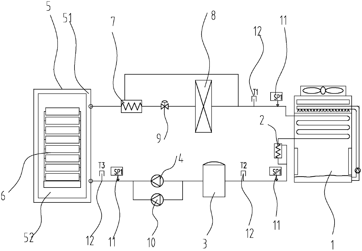
[0020] A cooling system for servers with different calorific values, including an evaporative condenser 1, a first subcooler 2, a liquid reservoir 3, a first fluorine pump 4, a liquid cooling box 5, and a second subcooler 7; The output end of the evaporative condenser 1 is connected to the first subcooler 2 through the pipeline, and the first subcooler 2 is connected to the liquid receiver 3 through the pipeline, and the liquid receiver 3 is connected to the first fluorine pump through the pipeline 4. The firs...


PUM


Abstract

The invention relates to a cooling system for servers with different calorific value, belonging to the technical field of server cooling, comprising an evaporative condenser, a first subcooler, a liquid reservoir, a first fluorine pump, a liquid cooling tank and a second subcooler; the output end of the evaporative condenser is connected to the first supercooler through a pipe, the first sub-cooler is connected with the liquid reservoir through a pipeline, a liquid reservoir is connecte with a first fluorine pump through a pipeline, the first fluorine pump is connected to the inlet of the liquid cooling box through a pipeline, the inlet of the liquid cooling box is connected with the outlet of the liquid cooling box through a channel arranged in the wall of the liquid cooling box, a firstcooling medium is arranged in the cold pool of the liquid cooling box, a high heat generating server is arranged in the first cooling medium, an outlet of the liquid cooling box is connected with a second subcooler through a pipe, the second subcooler is connected with a low heat generating server through a pipe, and the low heat generating server is connected with an input end of an evaporative condenser through a pipe. The invention is used for solving the technical problem of heat dissipation of different heat generating servers.

Description


Claims


Application Information

Patent Timeline
Owner ZHENGZHOU YUNHAI INFORMATION TECH CO LTD
Why Eureka
Try Eureka