
A Tag Antenna Solving the Interference Problem of Dense Placement

A technology for interference problems and tag antennas, which is applied to record carriers, instruments, and calculations used by machines, can solve problems such as the impact of antenna radiation on the environment, and achieve excellent anti-interference characteristics and high universality.

Active Publication Date: 2021-09-17
BEIJING INST OF COMP TECH & APPL
View PDF5 Cites 0 Cited by
  • Summary
  • Abstract
  • Description
  • Claims
  • Application Information

AI Technical Summary

Problems solved by technology

In addition, liquid is also a good conductor, which will also have a huge impact on the radiation environment of the antenna

Method used


Image

  • A Tag Antenna Solving the Interference Problem of Dense Placement
  • A Tag Antenna Solving the Interference Problem of Dense Placement
  • A Tag Antenna Solving the Interference Problem of Dense Placement

Examples


Embodiment Construction

[0018] In order to make the purpose, content, and advantages of the present invention clearer, the specific implementation manners of the present invention will be further described in detail below in conjunction with the accompanying drawings and embodiments.

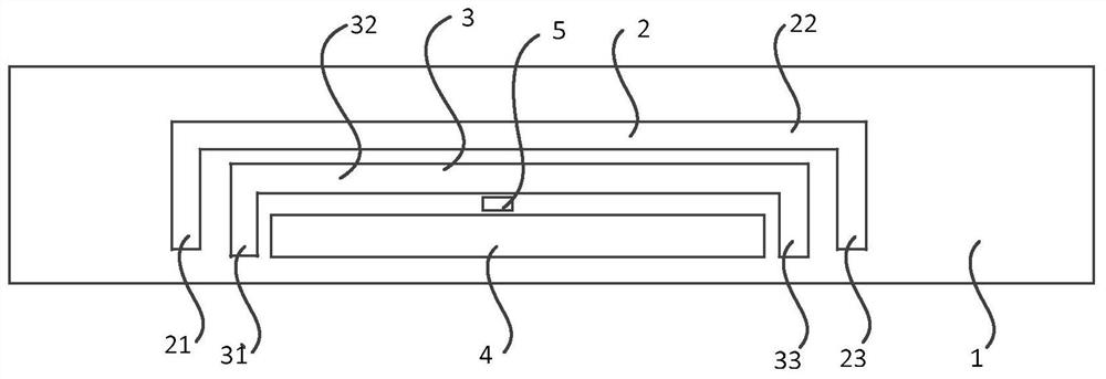
[0019] figure 1 Shown is a schematic diagram of a tag antenna that solves the problem of densely placed interference in the present invention, as figure 1 As shown, a tag antenna that solves the problem of densely placed interference includes: an antenna body 1 , a first hollow portion 2 , a second hollow portion 3 , a third hollow portion 4 and an antenna chip 5 .

[0020] like figure 1 As shown, the antenna body 1 is in a rectangular shape, and the first hollow part 2 includes: a first sub-hollow part 21, a second sub-hollow part 22 and a third sub-hollow part 23, the first sub-hollow part 21 and the third sub-hollow part 23 are all parallel to the wide side of the antenna body 1 , and the second sub-hollowout port...


PUM


Abstract

The present invention relates to a tag antenna that solves the problem of densely placed interference, which includes: the antenna body is in a rectangular shape, and the first hollow part includes: a first sub-hollowout part, a second sub-hollowout part and a third sub-hollowout part, the first sub-hollowout part Both the first sub-hollowout and the third sub-hollowout are parallel to the wide side of the antenna body, the second sub-hollowout is parallel to the long side of the antenna body, and the tail end of the first sub-hollowout is connected to a tail end of the second sub-hollowout. connection, the tail end of the third sub-hollow part is connected to the other end of the second sub-hollow part; Both the hollowed-out part and the sixth sub-hollowed-out part are parallel to the wide side of the antenna body, the fifth sub-hollowed-out part is parallel to the long side of the antenna body, and the tail end of the fourth sub-hollowed-out part is connected to a tail end of the fifth sub-hollowed-out part, The tail end of the sixth sub-hollow part is connected with the other tail end of the fifth sub-hollow part.

Description

technical field [0001] The invention relates to antenna technology, in particular to a tag antenna for solving the problem of intensive visit interference. Background technique [0002] With the development of Internet of Things technology, 900MHz RFID technology has more and more application fields, especially in the case of dense placement and liquid item management, the demand is urgent. Liquid items include bagged liquids, plastic bottled liquids, glass bottled liquids and metal canned liquids, etc. These liquid items need to apply RFID for registration, management, and destruction when they are produced, stored, sold, and used. [0003] The antenna material of the tag is aluminum foil, which is processed by etching process. The antenna is a space device from the circuit to the electric field, and the metal is equivalent to an electric wall in the electric field space, which will interfere with the propagation of electromagnetic waves. When placed densely, the antenna...

Claims


Application Information

Patent Timeline
Patent Type & Authority Patents(China)
IPC IPC(8): G06K19/077
CPCG06K19/07771G06K19/07773
Inventor 王璐静贾俊峰王颖
Owner BEIJING INST OF COMP TECH & APPL
Learn More