Wireless charging coil assembly

A coil assembly, wireless charging technology, applied in the direction of transformer/inductor coil/winding/connection, electrical components, transformer/inductor components, etc., can solve the problems of large impedance, increased transmission loss, small inductance, etc. The effect of improving efficiency, reducing impedance and increasing inductance

Active Publication Date: 2018-12-25
NUBIA TECHNOLOGY CO LTD
View PDF6 Cites 5 Cited by
  • Summary
  • Abstract
  • Description
  • Claims
  • Application Information

AI Technical Summary

Problems solved by technology

[0003] The purpose of the present invention is to provide a wireless charging coil assembly to solve the problems in the prior art that the PCB-designed mobile phone charging coil is thin but has a large impedance, which leads to increased transmission loss and compresses the space of the mobile phone charging coil to cause a small inductance value.

Method used


Image

  • Wireless charging coil assembly
  • Wireless charging coil assembly
  • Wireless charging coil assembly

Examples


Embodiment Construction

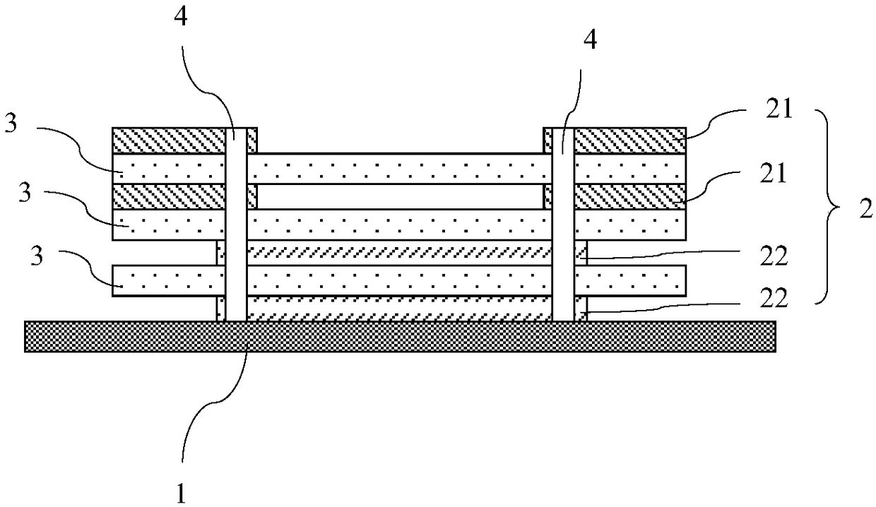
[0018] The structure of the wireless charging coil assembly of the present invention will be further described below in conjunction with the drawings and embodiments:

[0019] It should be understood that the specific embodiments described here are only used to explain the present invention, not to limit the present invention.

[0020] In the design of wireless charging coils, one of the key parameters is the quality factor Q value of the coil, which is directly related to the performance of the entire coil and the transmission loss. The Q value is calculated according to the following formula:

[0021]

[0022] Among them, the smaller the Q value, the lower the transmission efficiency of the coil, which affects the transmitted energy, and most of the energy is lost during the transmission process; the larger the Q value, the better the transmission efficiency of the coil. R is the coil impedance, L is the coil inductance. Based on the guidance of this formula, in the des...


PUM


Abstract

A wireless charging coil assembly includes a coil body, and the coil body includes a plurality of conductive coil layers arranged in longitudinal order and dielectric layers arranged between every twoadjacent conductive coil layers; each conductive coil layer includes a plurality of first conductive coil layers and at least one second conductive coil layer, each first conductive coil layer comprises at least one first coil segment, each second conductive coil layer comprises at least one second coil segment, projection of the first coil segment on each first conductive coil layer on the corresponding second conductive coil layer is spliced with the corresponding second coil segment to form a complete coil shape; the first coil segments corresponding to one other of different layers are connected in parallel with one other; the second coil segments corresponding to one other of the different layers are connected in parallel with one other; each of the first coil segments and each of the second coil segments are connected in series with each other. The wireless charging coil assembly of the invention adopts the form of multi-layer resistance coils being in parallel to reduce the impedance, and increases the inductance L through the coil segmentation, so as to improve the wireless charging efficiency.

Description

technical field [0001] The invention relates to the technical field of electronic products, in particular to a wireless charging coil assembly. Background technique [0002] In the mobile phone wireless charging design, because of the mobile phone ID and MD, there is not much space for the wireless charging coil, so the mobile phone wireless charging coil is usually required to be designed in the form of a PCB to meet the very thin requirement. However, the impedance of the thin coil is large, which will increase the transmission loss and affect its transmission power. If the space is compressed, the number of turns of the coil is less, and although the impedance is reduced, the inductance of the coil is also reduced, which will lead to a low quality factor Q value of the coil. Contents of the invention [0003] The purpose of the present invention is to provide a wireless charging coil assembly to solve the problems in the prior art that the PCB-designed mobile phone cha...

Claims


Application Information

Patent Timeline
Patent Type & Authority Applications(China)
IPC IPC(8): H01F38/14H01F27/28
CPCH01F27/28H01F27/2804H01F38/14H01F2027/2809
Inventor 陈增桂
Owner NUBIA TECHNOLOGY CO LTD
Why Eureka
Try Eureka