
Automatic die punching equipment

A technology of punching equipment and molds, applied in drilling/drilling equipment, metal processing equipment, manufacturing tools, etc., can solve the problems of inability to automatically complete punching work, high requirements for use, complex structure, etc., and improve the use value. , The effect of improving work performance and convenient operation

Pending Publication Date: 2018-12-28
宁波信宇模架有限公司
View PDF0 Cites 1 Cited by
  • Summary
  • Abstract
  • Description
  • Claims
  • Application Information

AI Technical Summary

Problems solved by technology

[0004] The object of the present invention is to provide a kind of mold automatic punching equipment, to solve the existing mold punching equipment proposed by the above-mentioned background technology that cannot automatically complete the punching work, and although some mold punching equipment can automatically complete the punching work, but Its structure is too complex and the requirements for use are relatively high

Method used


Image

  • Automatic die punching equipment
  • Automatic die punching equipment
  • Automatic die punching equipment

Examples


Embodiment Construction

[0019] The following will clearly and completely describe the technical solutions in the embodiments of the present invention with reference to the accompanying drawings in the embodiments of the present invention. Obviously, the described embodiments are only some, not all, embodiments of the present invention. Based on the embodiments of the present invention, all other embodiments obtained by persons of ordinary skill in the art without making creative efforts belong to the protection scope of the present invention.

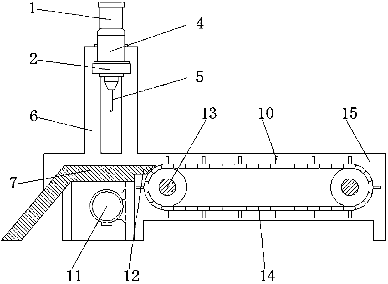
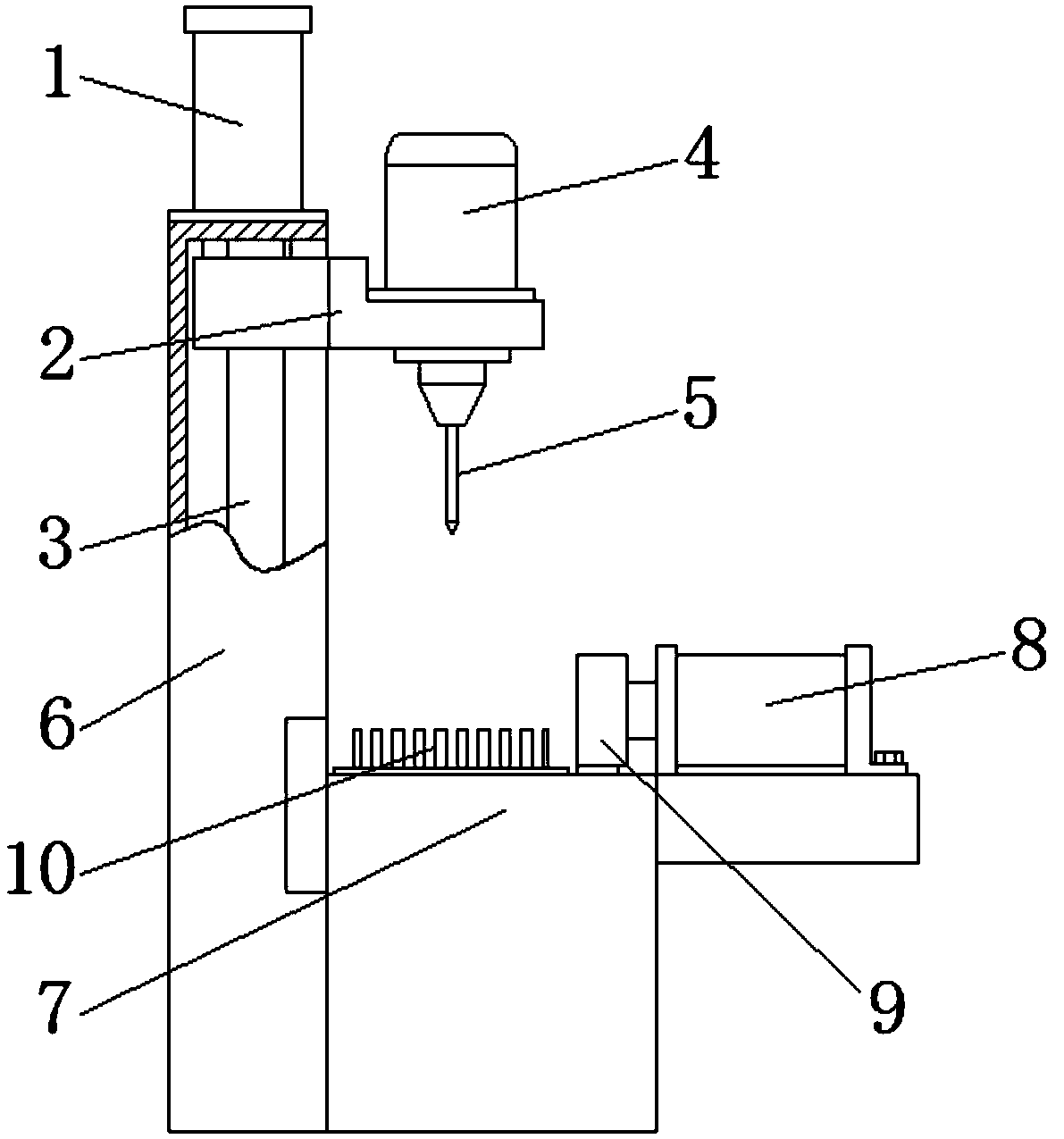
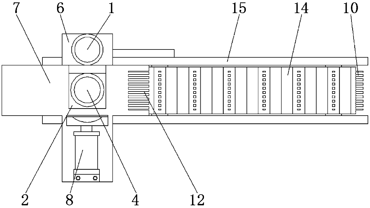
[0020] see Figure 1-4 , the present invention provides a technical solution: a mold automatic punching equipment, including a first electric cylinder 1, a sliding connection seat 2, a sliding rod 3, a first motor 4, a drill 5, a sliding body 6, a processing table 7, a first Two electric cylinders 8, compression heads 9, positioning teeth 10, second motor 11, feeding teeth 12, transmission wheels 13, transmission belts 14, limit sides 15 and compression belts ...


PUM


Abstract

The invention discloses automatic die punching equipment which comprises a first electric cylinder and a sliding connection seat. The sliding connecting seat is fixed onto the lower end of the first electric cylinder, a first motor is mounted on the upper side of the sliding connecting seat, the inner end of the sliding connecting seat is connected with a sliding body through a sliding rod, a processing table is fixed under the sliding body, a second electric cylinder is mounted on the upper edge of the processing table, a pressing head is fixed onto the front end of the second electric cylinder, a second motor is mounted on the lower side of the processing table, transmission wheels are connected to the outer end of the second motor, a transmission belt is connected to outer sides of thetransmission wheels, and positioning teeth are fixed on the outer surface of the transmission belt. The automatic die punching equipment is simple in structure, convenient in operation and high in practical value, automatic feeding of the equipment is achieved by the arrangement of the transmission belt, and dies can be automatically punched.

Description

technical field [0001] The invention relates to the technical field of mold processing, in particular to automatic punching equipment for molds. Background technique [0002] Mold punching equipment, as the name implies, is the equipment for processing holes in the mold. Although there are many mature mold punching equipment, some mold punching equipment cannot automatically complete the punching work, and some mold punching equipment although It can automatically complete the punching work, but its structure is too complicated and the requirements for use are relatively high. [0003] So we propose a mold automatic punching equipment in order to solve the problems raised above. Contents of the invention [0004] The object of the present invention is to provide a kind of mold automatic punching equipment, to solve the existing mold punching equipment proposed by the above-mentioned background technology that cannot automatically complete the punching work, and although s...

Claims


Application Information

Patent Timeline
Patent Type & Authority Applications(China)
IPC IPC(8): B23B41/00
CPCB23B41/00
Inventor 王德助
Owner 宁波信宇模架有限公司
Learn More