Multi-shaft-hole automatic aligning method based on laser tracker

A laser tracker and shaft hole technology, which is used in metal processing, metal processing equipment, manufacturing tools, etc., can solve the research on multi-axis hole alignment of large parts and components has not been published, and the automatic assembly of large parts is still in the research stage , has not yet been practical and other problems, to achieve the effect of high-precision automatic alignment, stable and efficient assembly operations, and make up for the lack of absolute motion

Active Publication Date: 2018-12-28
TSINGHUA UNIV
View PDF6 Cites 9 Cited by
  • Summary
  • Abstract
  • Description
  • Claims
  • Application Information

AI Technical Summary

Problems solved by technology

[0003] The existing assembly of large parts is mainly completed by manual assembly, which is inefficient and the assembly accuracy is not high
Most of the automated assembly of large parts based on robots is still in the research stage and has not yet been practical, and the research on the alignment of multi-axis holes in large parts has not yet been published.

Method used


Image

  • Multi-shaft-hole automatic aligning method based on laser tracker
  • Multi-shaft-hole automatic aligning method based on laser tracker
  • Multi-shaft-hole automatic aligning method based on laser tracker

Examples


Embodiment Construction

[0052] The present invention proposes an automatic alignment method for multi-axis holes based on a laser tracker. The present invention will be further described in detail below in conjunction with the accompanying drawings and specific embodiments.

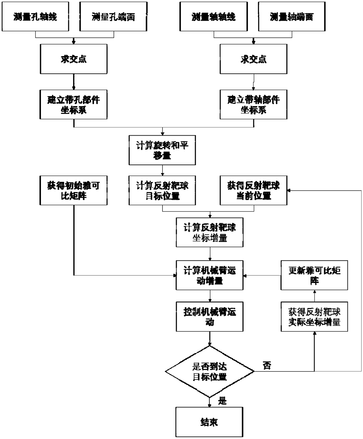
[0053] The present invention proposes an automatic alignment method for multi-axis holes based on a laser tracker. The overall process is as follows figure 1 shown, including the following steps:

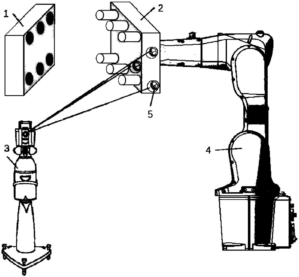
[0054] 1) Building an automatic multi-axis hole alignment system; the multi-axis hole automatic alignment system includes: a laser tracker, a mechanical arm and a computer. The laser tracker and the mechanical arm are respectively connected to the computer by wire or wirelessly. Among them, the laser tracker and the computer can be of any type, and the mechanical arm can be greater than six degrees of freedom.

[0055] The laser tracker is used in conjunction with a reflective target ball or a T-Prob to measure the parts with holes ...


PUM


Abstract

The invention provides a multi-shaft-hole automatic aligning method based on a laser tracker, and belongs to the technical field of large part assembly control. The multi-shaft-hole automatic aligningmethod comprises the steps that firstly, a multi-shaft-hole automatic aligning system constituted by the laser tracker, a mechanical arm and a computer is set up, and a shaft part is mounted on the end face of the mechanical arm; a shaft part coordinate system and a perforated part coordinate system are built, and a rotation matrix and a translation vector between the two coordinate systems are obtained; four non-collinear reflecting target spheres are mounted on the shaft part, and the target positions corresponding to all the target spheres are calculated; and an initial jacobian matrix ofthe mechanical arm is obtained; movement of the mechanical arm is controlled in an iterating mode from the initial position, thus the shaft part gets close to the perforated part gradually, and when the four reflecting target spheres reach the target portions, the shaft part and the perforated part are aligned. Movement of the mechanical arm is controlled in a closed-loop mode through measuring data of the laser tracker, multi-shaft-hole high-precision automatic aligning can be achieved, and the assembly efficiency and robustness are improved.

Description

technical field [0001] The invention belongs to the technical field of assembly control of large parts, and in particular relates to an automatic alignment method for multi-axis holes based on a laser tracker. Background technique [0002] Multi-axis hole connection is a commonly used assembly connection method in the field of large-scale component assembly. One of the two parts to be assembled has multiple holes, which is called a component with holes; the other has multiple axes corresponding to the holes, which is called For shaft parts. By inserting a plurality of shafts on the part with shafts into the corresponding holes on the part with holes, the cooperation of the two parts can be realized, and then the positioning connection is completed by locking nuts or pins, so as to complete the assembly. [0003] The existing assembly of large parts is mainly completed by manual assembly, which is inefficient and the assembly accuracy is not high. Most of the automatic asse...

Claims


Application Information

Patent Timeline
Patent Type & Authority Applications(China)
IPC IPC(8): B23P19/12
CPCB23P19/12
Inventor 徐静陈恳刘炽成吴丹宋立滨
Owner TSINGHUA UNIV
Why Eureka
Try Eureka