Quasi-resonance converter synchronous rectification circuit

A technology of synchronous rectification and converter, which is applied in the direction of DC power input conversion to DC power output, AC power input conversion to DC power output, instruments, etc. Self-driving mode and other problems, to overcome the effect of large conduction loss, small switching loss, low conduction resistance and conduction loss

Active Publication Date: 2013-09-04
NO 24 RES INST OF CETC
View PDF2 Cites 24 Cited by
  • Summary
  • Abstract
  • Description
  • Claims
  • Application Information

AI Technical Summary

Problems solved by technology

In recent years, the use of synchronous rectification technology has been widely used in PWM DC / DC converters, and the efficiency has generally been greatly improved; while the quasi-resonant converter is different from the PWM converter, it uses the leakage inductance of the transformer and the junction capacitance of the power semiconductor switch. The current and voltage waveforms are quasi-sine waves, and synchronous rectification is not as easy to implement as PWM converters: on the one hand, high-frequency quasi-resonant converters work at high frequencies, and synchronous rectification has fast drive speed and large losses, making it difficult to design drive control circuits; The synchronous rectifier tube of the quasi-resonant converter cannot directly obtain the driving signal from the power transformer, and it is difficult to adopt a self-driving method. It is necessary to design a dedicated control circuit or a custom IC to achieve synchronous driving.

Method used


Image

  • Quasi-resonance converter synchronous rectification circuit
  • Quasi-resonance converter synchronous rectification circuit
  • Quasi-resonance converter synchronous rectification circuit

Examples


Embodiment 1

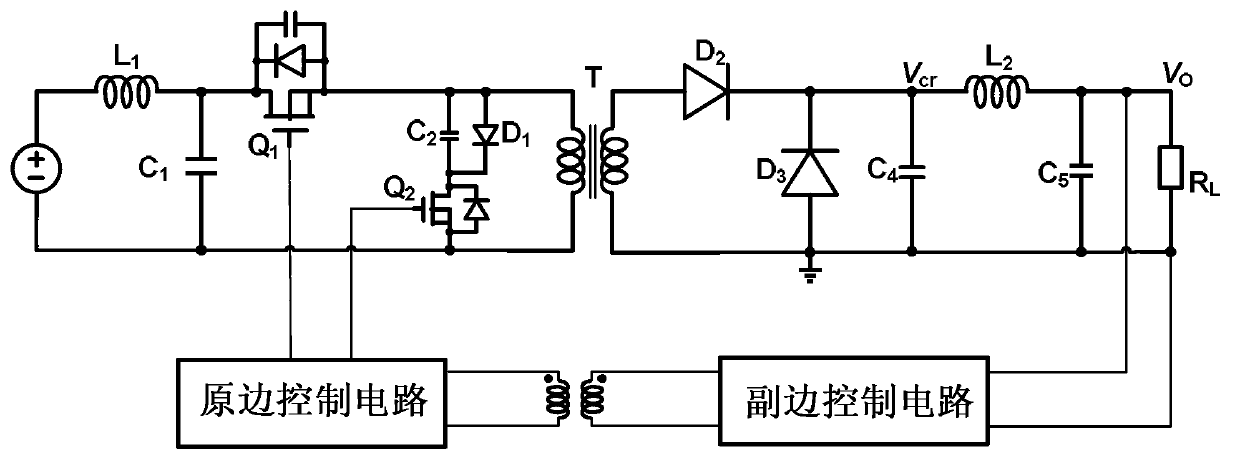
[0056] figure 1 It is a circuit diagram of a traditional quasi-resonant forward converter. The secondary circuit of the transformer T is rectified by a diode. Due to the conduction voltage drop of the diode (U D ) is usually large, generally above 0.5V, especially in the output current (I F ) is larger (tens of amperes or even nearly a hundred amperes), the on-state voltage drop is greater, and the diode conduction loss is

[0057] P DLoss =U D ×I F …………………………………………………………(1)

[0058] It can be seen from the above formula that the conduction loss of the diode is proportional to the forward current, the greater the output current, the greater the loss; and the parallel connection of multiple diodes cannot reduce the conduction loss; therefore, figure 1 The conventional quasi-resonant converter shown is not efficient enough for high power applications, especially for low voltage / high current output.

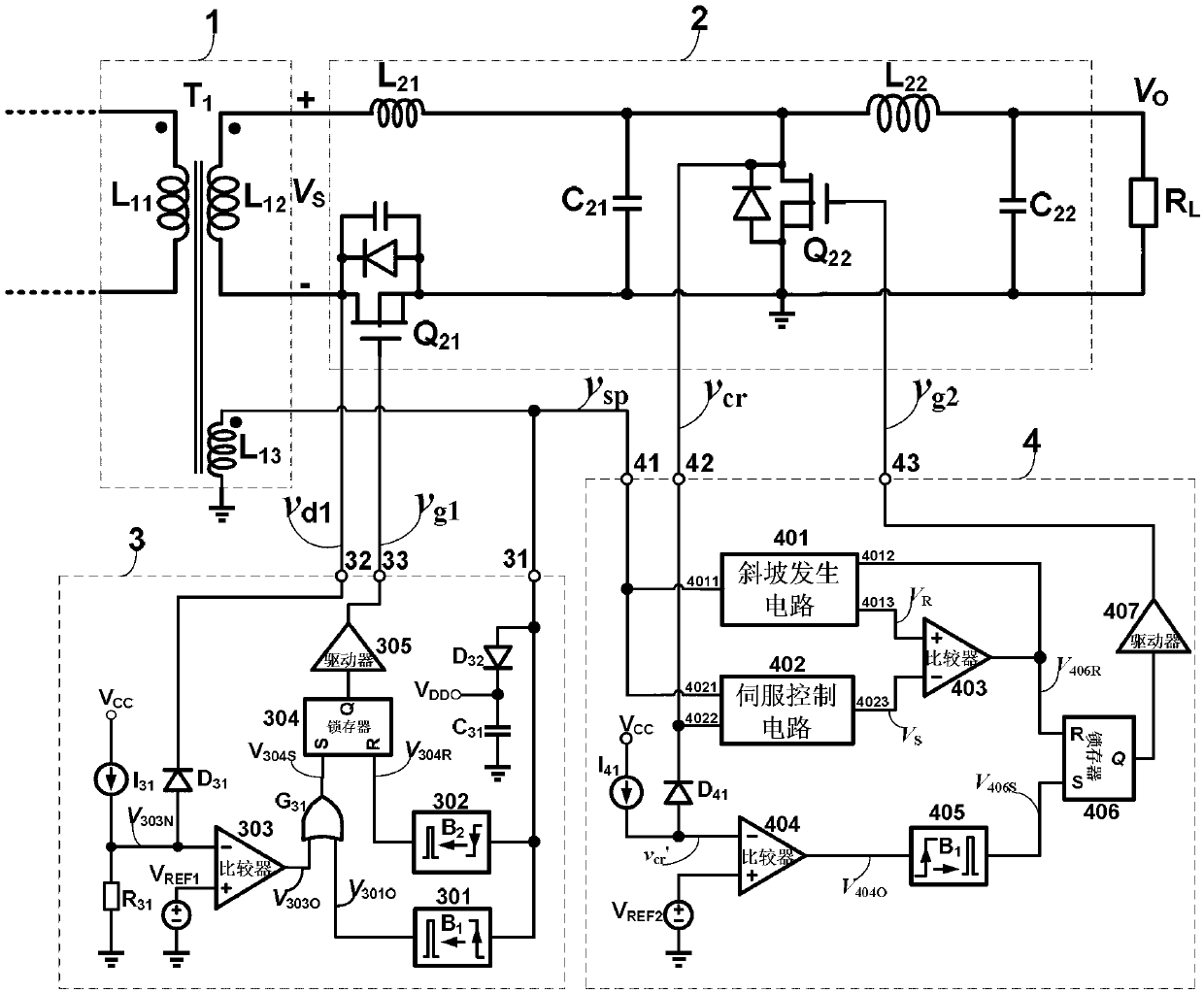
[0059] figure 2 is the synchronous rectification circuit diagram of th...

Embodiment 2

[0084] This embodiment describes in detail the principle of the quasi-resonant converter synchronous rectification circuit:

[0085] The power transformer T1 includes at least the primary winding L 11 , Secondary winding L 12 and auxiliary winding L 13 ;Primary winding L 11 and the secondary winding L 12 Realize input / output electrical isolation and voltage conversion, auxiliary winding L 13 Provide DC bias voltage and synchronous signal for the control circuit (ie rectifier tube control circuit 3 and freewheel tube control circuit 4).

[0086] The secondary switch circuit 2 includes a resonant inductor L 21 , Resonant capacitance C 21 , filter inductance L 22 , filter capacitor C 22 , rectifier tube Q 21 and freewheel Q 22 ; where the rectifier tube Q 21 and freewheel Q 22 It is not limited to the use of MOSFET type controllable switches, and other types of controllable switches, such as BJT, IGBTS, etc., can also be used. The on-resistance of the controllable sw...


PUM


Abstract

The invention discloses a quasi-resonance converter synchronous rectification circuit which comprises a power transformer, a secondary power switch circuit, a rectification tube control circuit and a follow current tube control circuit. Detection to the power transformer is used for achieving a no-voltage connecting function and a no-voltage disconnecting function on a rectification tube in the secondary power switch circuit. The quasi-resonance converter synchronous rectification circuit aims at solving the problem that a traditional quasi-resonance converter using diode rectification is large in connecting loss and low in efficiency when used in a large current output applying occasion. The quasi-resonance converter synchronous rectification circuit can achieve no-voltage connecting and no-voltage disconnecting of the rectification tube and a follow current tube under the conditions of load changes, input voltage changes, temperature changes and the like, has the self-adaptation soft switching function, is high in conversion efficiency, contributes to high frequency and miniaturization of a converter, and can be widely applied to manufacturing power sources for the industry, the aviation and the communication.

Description

technical field [0001] The invention relates to the technical field of DC / DC converters, in particular to a quasi-resonant converter synchronous rectification circuit. Background technique [0002] DC / DC converters can be divided into non-isolated DC converters and DC converters with transformer isolation according to whether the input / output is electrically isolated, and can be divided into pulse width modulation (PWM) converters and pulse frequency modulation (PFM) according to the modulation method. converter; but no matter what kind of converter, efficiency improvement and high frequency are always important directions for the development of DC / DC converters. The quasi-resonant converter based on PFM modulation that appeared in the 1980s can realize zero-voltage and zero-current switching (ZVS, ZCS) of the power switch tube, which greatly reduces the switching loss of the power switch tube and improves the switching efficiency of the converter. frequency and efficiency....

Claims


Application Information

Patent Timeline
Patent Type & Authority Applications(China)
IPC IPC(8): H02M7/217H02M3/155
CPCY02P80/10
Inventor 章治国周林胡刚毅余海生吴限王强杨占军张纯亚
Owner NO 24 RES INST OF CETC
Why Eureka
Try Eureka