
A mobile charging device for a new energy vehicle

A technology for new energy vehicles and charging equipment, applied in electric vehicles, electric traction, vehicle parts, etc., can solve problems such as charging equipment can only be left idle in parking lots, electric vehicles cannot be charged, and vehicles are maliciously preempted, etc., to extend the length of , The effect of increasing the moving range and convenient charging

Inactive Publication Date: 2018-12-28
潍坊华高信息科技有限公司
View PDF0 Cites 1 Cited by
  • Summary
  • Abstract
  • Description
  • Claims
  • Application Information

AI Technical Summary

Problems solved by technology

[0004] The purpose of the present invention is to provide a charging device for new energy vehicles that is easy to move, so as to solve the problem that the charging devices for new energy vehicles proposed in the above-mentioned background technology are basically arranged behind the garage, and the charging parking spaces with charging piles often It will be maliciously preempted by non-charging cars, causing the charging equipment to be idle in the parking lot, or the fully charged car still stays in the charging parking space, resulting in the problem that the electric car that needs to be charged cannot be charged

Method used


Image

  • A mobile charging device for a new energy vehicle
  • A mobile charging device for a new energy vehicle
  • A mobile charging device for a new energy vehicle

Examples


Embodiment Construction

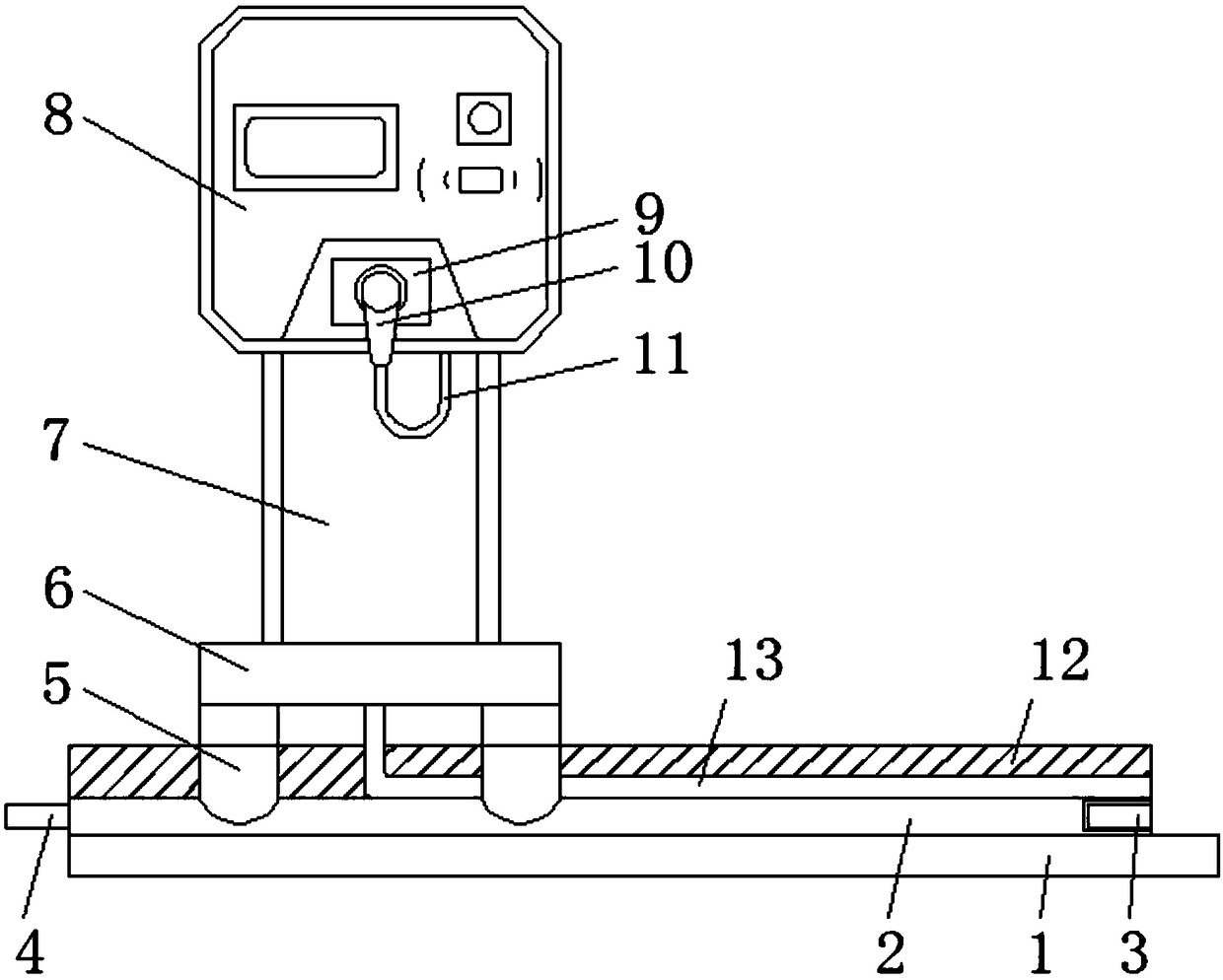
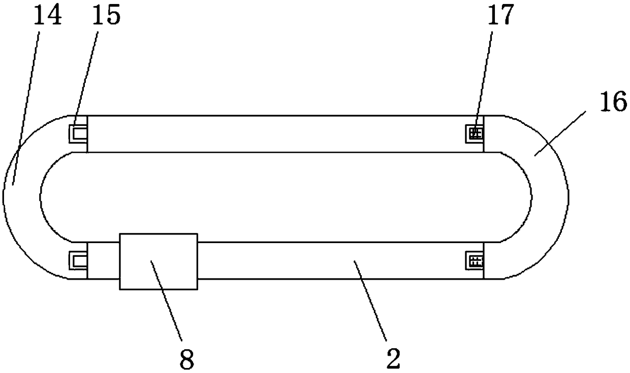
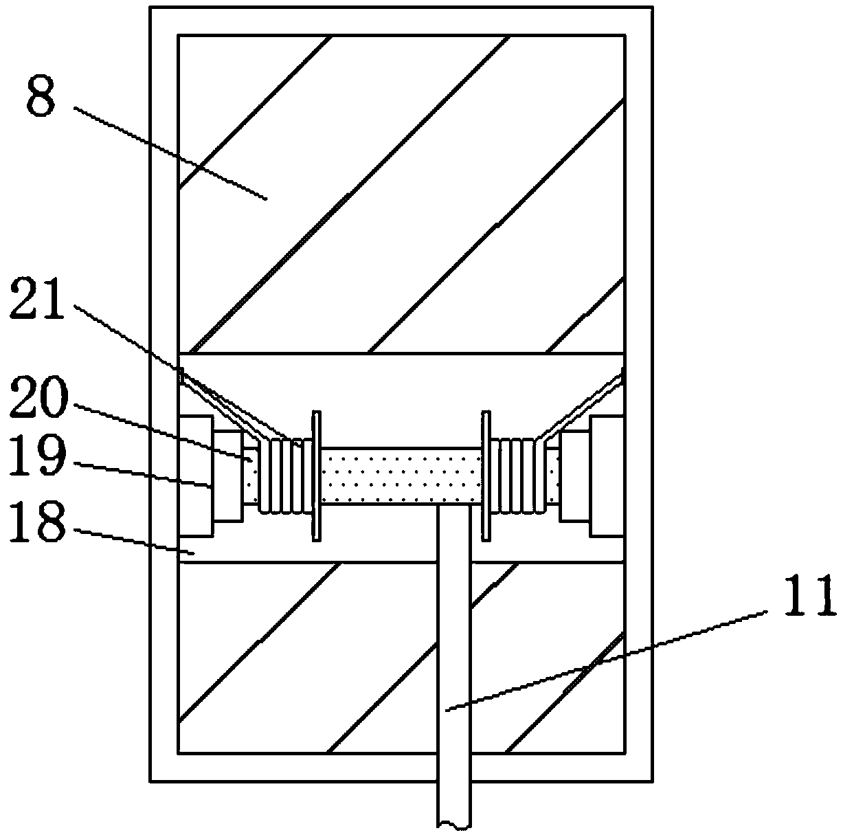
[0018] The following will clearly and completely describe the technical solutions in the embodiments of the present invention with reference to the accompanying drawings in the embodiments of the present invention. Obviously, the described embodiments are only some, not all, embodiments of the present invention. Based on the embodiments of the present invention, all other embodiments obtained by persons of ordinary skill in the art without making creative efforts belong to the protection scope of the present invention.

[0019] see Figure 1-3 , the present invention provides a technical solution: a charging device for new energy vehicles that is easy to move, including a mounting plate 1, a first sliding track 2, a first groove 3, a first bump 4, a sliding block 5, and a mounting frame 6. Support pile 7, charging box 8, charging interface 9, charging gun 10, connecting wire 11, through groove 12, connecting hose 13, second sliding track 14, second groove 15, third sliding tra...


PUM


Abstract

The invention discloses a mobile charging device for a new energy vehicle, includes a mounting plate and a connecting shaft, the upper end of the mounting plate is provided with a first sliding rail,and the left side of the inner lower end of the first slide rail is provided with a first groove, The first groove and the first sliding rail are integrally connected by pressing, the left lower end of the first sliding rail is embedded with a first protrusion, and the front side of the first sliding rail is connected with a sliding block, the first protrusion and the first sliding rail are welded, and the sliding block and the first sliding rail are slidably connected. The new energy vehicle charging device is provided with a first groove which is the same size as the first protrusion, so that the first protrusion can be inserted into the inside of the first groove, so that a plurality of first sliding rails can be coincided with each other and assembled, and the sliding distance range ofthe charging device can be increased.

Description

technical field [0001] The invention relates to the technical field of charging equipment for new energy vehicles, in particular to a charging equipment for new energy vehicles that is easy to move. Background technique [0002] Although new energy vehicles are more environmentally friendly, charging is cumbersome. Now many places will install charging equipment, that is, charging piles. Charging piles are generally installed in public buildings or parking lots in residential areas, and can be used according to different voltage levels. One type of electric vehicle charging, in which the input end of the charging pile is directly connected to the AC power grid, and the output end is equipped with a charging gun for the convenience of users. [0003] The charging equipment for new energy vehicles on the market is basically installed behind the garage. The charging parking spaces with charging piles are often maliciously seized by non-charging cars, resulting in charging equip...

Claims


Application Information

Patent Timeline
IPC IPC(8): B60L11/18
Inventor 徐元芳
Owner 潍坊华高信息科技有限公司
Learn More