Chain wheel conveyor

A sprocket conveyor and conveyor technology, applied in the field of mechanical transportation, can solve the problems of inconvenient installation and disassembly, time-consuming and laborious, etc., and achieve the effect of convenient maintenance, installation and disassembly, simple equipment structure and quick maintenance

Pending Publication Date: 2018-12-28
HUNAN XIANGHENG SALT CHEM
View PDF0 Cites 4 Cited by
  • Summary
  • Abstract
  • Description
  • Claims
  • Application Information

AI Technical Summary

Problems solved by technology

[0002] The sprocket transmission group is often used in mechanical transportation, but the transmission mode of the sprocket conveyor in the existing technology generally uses a chain to drive the sprocket to rotate, and then drives the idler to rotate, wherein the idler is equipped with an inner sprocket and an outer sprocket. The sprocket has two sprockets, the inner sprocket is connected with the reduction motor through the chain, and the outer sprocket is connected with the outer sprocket of the next idler through the chain (refer to the attached figure 1 ), one set of one, which will result in that if one roller or sprocket is damaged, 3~4 rollers need to be removed when replacing, which is inconvenient to install and disassemble, time-consuming and laborious

Method used


Image

  • Chain wheel conveyor
  • Chain wheel conveyor
  • Chain wheel conveyor

Examples


Embodiment 1

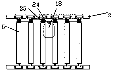
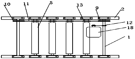
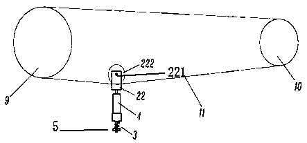
[0019] refer to figure 2 , a sprocket conveyor, comprising a conveyor bracket 2, a long chain 11, a transmission device and a plurality of idler rollers 5, one side end of the conveyor bracket is provided with a drive sprocket 9, and the other end of the opposite drive sprocket 9 A driven sprocket 10 is provided, and the driving sprocket 9 and the driven sprocket 10 are connected by a long chain 11. One end of the idler 5 is provided with a rotating sprocket 13, and the long chain 11 is placed at the bottom of the rotating sprocket 13, and is connected with the The rotating sprocket 13 is meshed, the two ends of the idler roller 5 are fixed on the conveyor bracket 2, the transmission device is connected with the driving sprocket 9, the transmission device includes a reduction motor 18, the main shaft 1 and the driving sprocket 12, and the main shaft 1 is fixed on the conveyor On the machine support 2, the drive sprocket 12 is arranged on the main shaft 1, and the reduction mo...

Embodiment 2

[0023] refer to Figure 4 , a sprocket conveyor in this embodiment, compared with Embodiment 1, has the following distinguishing technical features:

[0024] Both ends of the idler roller 5 are provided with rotating sprockets 13, both ends of the conveyor bracket 2 are provided with drive sprockets 9, and the opposite end of the drive sprocket 9 is provided with a pair of corresponding driven sprockets 10. Other structures are the same.

[0025] In the sprocket conveyor of this embodiment, since both ends of the idler rollers are equipped with rotating sprockets, which are simultaneously driven by the long chains arranged on both sides of the conveyor bracket, it is beneficial for the rotating sprockets at the ends of the idler rollers to rotate the long chain. The balanced distribution of the active force makes the idler roller rotate more smoothly, which significantly improves the conveying stability of the sprocket conveyor; and reduces the wear between the rotating sproc...


PUM


Abstract

The invention discloses a chain wheel conveyor. The chain wheel conveyor comprises a conveyor support, a reel chain, a transmission gear and a plurality of rollers. A driving chain wheel is disposed on the end portion of at least one side of the conveyor support, and a driven chain wheel is disposed at the other end, relative to the driving chain wheel, of the conveyor support. The driving chain wheel is connected with the driven chain wheel through the reel chain, and rotating chain wheels are arranged on the end portions of the rollers. The reel chain is placed on the lower portions of the rotating chain wheels, and the reel chain meshes with the rotating chain wheels. The two ends of the rollers are fixed to the conveyor support. The transmission gear is connected with the driving chainwheel, and drives the rotation of the driving chain wheel, thereby sequentially driving the transmission of the reel chain and the rotation of the rotating chain wheels. The chain wheel conveyor hasa simple structure, rapid maintenance, convenient installation and disassembly and a long service life.

Description

technical field [0001] The invention relates to the field of mechanical conveying, in particular to a sprocket conveyor. Background technique [0002] The sprocket transmission group is often used in mechanical transportation, but the transmission mode of the sprocket conveyor in the existing technology generally uses a chain to drive the sprocket to rotate, and then drives the idler to rotate, wherein the idler is equipped with an inner sprocket and an outer sprocket. The sprocket has two sprockets, the inner sprocket is connected with the reduction motor through the chain, and the outer sprocket is connected with the outer sprocket of the next idler through the chain (refer to the attached figure 1 ), one set of one, which will result in that if one roller or sprocket is damaged, 3~4 rollers need to be removed when replacing, which is inconvenient to install and disassemble, time-consuming and laborious. Contents of the invention [0003] The technical problem to be sol...

Claims


Application Information

Patent Timeline
Patent Type & Authority Applications(China)
IPC IPC(8): B65G13/07
CPCB65G13/07
Inventor 龙海玲唐世俭陈圣儒刘绍云
Owner HUNAN XIANGHENG SALT CHEM
Why Eureka
Try Eureka