
Surface connecting top line and manufacturing mold thereof

A mold and top line technology, applied in the direction of architecture, building structure, etc., can solve the problem that it cannot be installed on the indoor top floor and wall at the same time, the stability of the decorative line and the wall cannot be guaranteed, and the structural integrity of the decorative line cannot be guaranteed. and other problems, to achieve the effect of convenient interior decoration, good decorative effect and enhanced structural strength

Inactive Publication Date: 2018-12-28
湖州天辛环保科技有限公司
View PDF7 Cites 0 Cited by
  • Summary
  • Abstract
  • Description
  • Claims
  • Application Information

AI Technical Summary

Problems solved by technology

[0002] The surface connection top line is a kind of decorative line, which can be used to decorate walls and ceilings by connecting top lines of different shapes together to form various shapes. The connection at the seam is inconvenient, often leaving gaps, and the cross-sectional shape is difficult to control, and it is only suitable for the decoration of a single wall, and cannot be installed on the top floor and the wall at the same time
[0003] The Chinese patent with the authorized notification number CN207092473U discloses a corner decorative line, which is separated from the decorative board by the base board, so that the decorative boards of different designs and styles can be matched and replaced without changing the base board, thereby quickly and simply realizing various decorations. Different decorative effects, one thing with multiple decorations, which reduces the cost, but the stability of the connection between the decorative line and the wall cannot be guaranteed, and the structural integrity of the decorative line cannot be guaranteed when the material is deformed by the external temperature

Method used


Image

  • Surface connecting top line and manufacturing mold thereof
  • Surface connecting top line and manufacturing mold thereof
  • Surface connecting top line and manufacturing mold thereof

Examples


Embodiment Construction

[0025] The following will clearly and completely describe the technical solutions in the embodiments of the present invention with reference to the accompanying drawings in the embodiments of the present invention. Obviously, the described embodiments are only some, not all, embodiments of the present invention. Based on the embodiments of the present invention, all other embodiments obtained by persons of ordinary skill in the art without making creative efforts belong to the protection scope of the present invention.

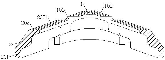
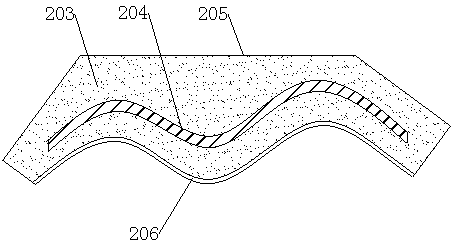
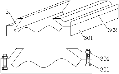
[0026] see Figure 1-5 , the present invention provides a technical solution: a surface connection top line and its production mold, including corner line 2, line mold 3, plywood 4 and corner connector 1, the left and right sides of corner connector 1 are fixedly connected with corners Line 2, the upper end surface of the corner line 2 is fixedly connected with the top plate 202, and the upper end surface of the top plate 202 is closely attached to the cemente...


PUM


Abstract

The invention discloses a surface connecting top line and a manufacturing mold thereof and belongs to the field of decoration materials. The technical scheme includes that the surface connecting top line comprises corner lines, a line mold, a clamp plate and a corner connector, the corner lines are fixedly connected to left and right sides of the corner connector, the upper end face of each cornerline is fixedly connected with a top plate, the upper end face of each top plate is tightly adhered with a cementing panel, the interior of each corner line is tightly adhered with gypsum filler, andglass fiber is penetratingly connected in the gypsum filler. By the arrangement of the cementing panels on the top plates, stability in mounting of the corner lines is strengthened, structural strength of the corner lines is enhanced through the glass fiber, great convenience is brought to indoor decoration since grooves used for arranging indoor lines are formed between oblique panels and corners, the corner lines are fixed through the top plates and side panels, the corner lines between two side walls are connected through the corner connector, and mounting of the corner lines is further facilitated.

Description

technical field [0001] The invention relates to the field of decoration materials, in particular to a surface-connected top wire and a mold for making the same. Background technique [0002] The surface connection top line is a kind of decorative line, which can be used to decorate walls and ceilings by connecting top lines of different shapes together to form various shapes. The connection at the seam is inconvenient, there are often gaps, and the cross-sectional shape is difficult to control, and it is only suitable for the decoration of a single wall, and cannot be installed on the top floor and the wall at the same time. [0003] The Chinese patent with the authorized notification number CN207092473U discloses a corner decorative line, which is separated from the decorative board by the base board, so that the decorative boards of different designs and styles can be matched and replaced without changing the base board, thereby quickly and simply realizing various decorat...

Claims


Application Information

Patent Timeline
IPC IPC(8): E04F19/04
CPCE04F19/0436
Inventor 沈辉
Owner 湖州天辛环保科技有限公司
Learn More