
A hand-held automatic steel wire binding equipment

A hand-held, automatic technology, applied in the processing of building materials, construction, building structure, etc., can solve the problems of complex and artificial wire pulling structure, and achieve the effect of reducing the amount of operation and bundling firmly

Active Publication Date: 2020-11-06
广西盛隆钢铁材料研究院有限公司
View PDF5 Cites 0 Cited by
  • Summary
  • Abstract
  • Description
  • Claims
  • Application Information

AI Technical Summary

Problems solved by technology

[0004] The purpose of the present invention is to provide a split-type fruit tree infusion tree nail to solve the technical problems in the prior art that steel wire binding equipment needs manual wire drawing and complex structure

Method used


Image

  • A hand-held automatic steel wire binding equipment
  • A hand-held automatic steel wire binding equipment
  • A hand-held automatic steel wire binding equipment

Examples


Embodiment Construction

[0031] The technical solutions of the present invention will be clearly and completely described below in conjunction with the accompanying drawings. Apparently, the described embodiments are some of the embodiments of the present invention, but not all of them.

[0032] The components of the embodiments of the invention generally described and shown in the figures herein may be arranged and designed in a variety of different configurations. Accordingly, the following detailed description of the embodiments of the invention provided in the accompanying drawings is not intended to limit the scope of the claimed invention, but merely represents selected embodiments of the invention.

[0033] Based on the embodiments of the present invention, all other embodiments obtained by persons of ordinary skill in the art without making creative efforts belong to the protection scope of the present invention.

[0034] In the description of the present invention, it should be noted that the...


PUM


Abstract

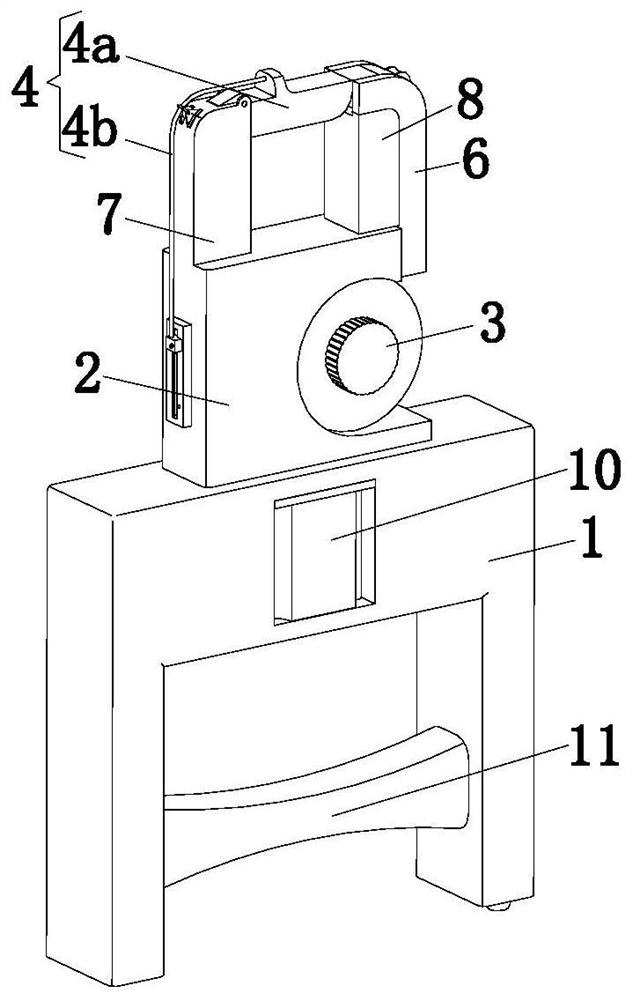
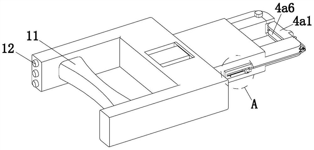
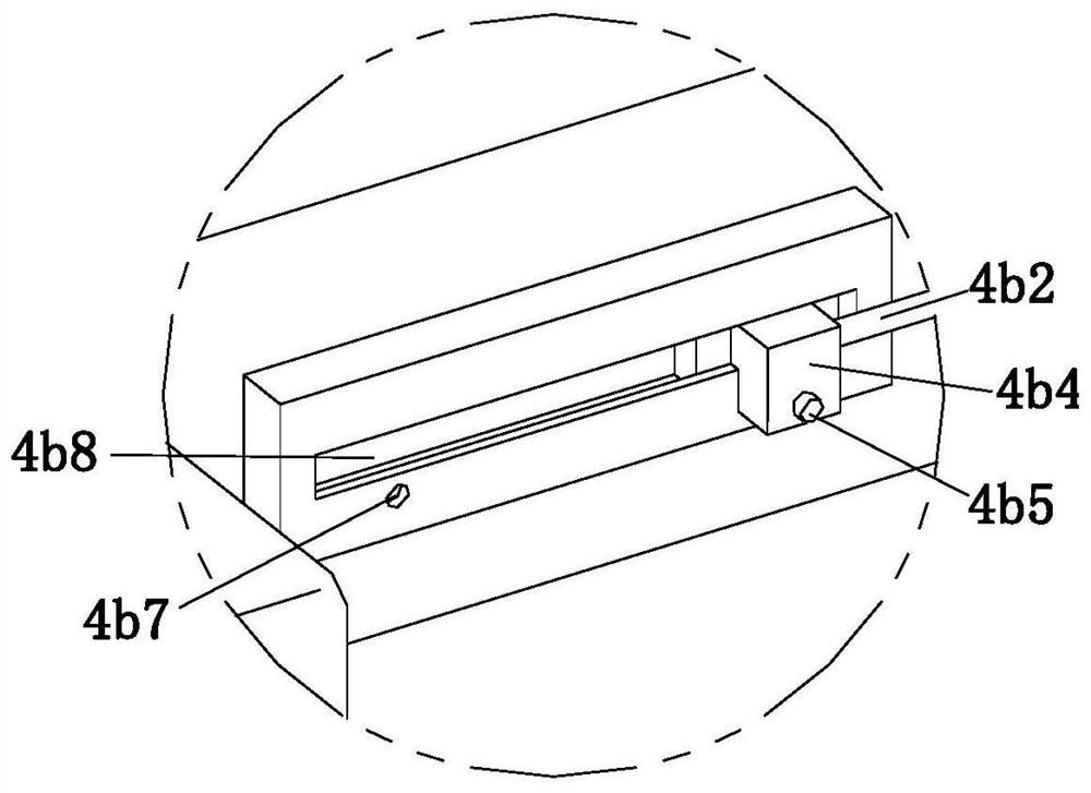
The invention discloses hand-held automatic steel wire strapping equipment, and belongs to the technical field of building construction auxiliary equipment. The hand-held automatic steel wire strapping equipment comprises a first mounting block, a second mounting block, a wire discharging mechanism, a limiting mechanism and a cutting mechanism, wherein the second mounting block is positioned at the front end of the first mounting block and is connected with the first mounting block in a rotary manner; a first connecting column and a second connecting column are arranged at the front end of thesecond mounting block; the wire outlet mechanism and the limiting mechanism are fixedly connected with the first connecting column and the second connecting column respectively; the limiting mechanism comprises a limiting component and a linkage component; the linkage component is mounted on the side of the second mounting block and is connected with the limiting component; the cutting mechanismcomprises a driving component and a cutting component; the driving component is connected with the cutting component; and the wire discharging mechanism comprises a feeding component and a wire discharging component. According to the invention, the working procedures of wire discharging, strapping and cutting can be automatically completed without manual auxiliary operation, so that the strappingefficiency of steel bars is higher, the structure is simple, and the cost and maintenance difficulty can be reduced.

Description

technical field [0001] The invention relates to the technical field of building construction auxiliary equipment, in particular to a hand-held automatic steel wire binding equipment. Background technique [0002] The commonly used building materials in the use of steel bars in the construction process, the steel bars need to be fixed together by binding when they are used, the traditional binding method is to use steel wires for binding, this method needs to cut the steel wires manually, and then wind the steel wires around the steel bars Then twist the two ends of the steel wire together. This method is time-consuming and laborious, and the binding speed is very slow. [0003] Chinese Patent No. CN106285012B discloses an automatic steel bar binding machine, including a frame, and a wire binding mechanism, a power mechanism, a wire feeding mechanism, a wire cutting mechanism, jaws and a guide mechanism respectively arranged on the frame, Wire bending mechanism and wire twis...

Claims


Application Information

Patent Timeline
Patent Type & Authority Patents(China)
IPC IPC(8): E04G21/12
CPCE04G21/123
Inventor 董淑翠张海亭何碧侠
Owner 广西盛隆钢铁材料研究院有限公司
Learn More