Running-in device suitable for micro-small ball screw pair and running method thereof

A ball screw pair, micro-miniature technology, applied in the direction of machine gear/transmission mechanism testing, etc., can solve the problems of screw shaft system temperature rise, large coaxiality error, radial bias load increase, etc., to achieve running High efficiency, simple structure, and reduced deflection

Pending Publication Date: 2018-12-28
NANJING UNIV OF SCI & TECH +1
View PDF9 Cites 2 Cited by
  • Summary
  • Abstract
  • Description
  • Claims
  • Application Information

AI Technical Summary

Problems solved by technology

This running-in method is inefficient and cannot meet the needs of the current ball screw
And in the structural layout of the running-in machine, most of the existing running-in devices are horizontal, with single screw running-in
For the lead screw installed on the horizontal running-in machine, the coaxiality error of the head and tailstock is relatively large, which causes the increase of the deflection of the lead screw, the increase of the radial bias load, and the temperature rise and thermal deformation of each link of the lead screw shaft system. A series of serious consequences, such as the increase of Yamato transmission torque, lead to overload and overheating of the servo motor, and the servo system alarms, affecting the normal operation of the machine tool
And the running-in efficiency of a single screw is much lower than the running-in efficiency of multiple screws at the same time
[0003] To sum up, there is no special equipment at this stage to run-in the miniature ball screw pair. The existing device is suitable for medium and large ball screw pairs, and it is a single-screw run-in, which is inefficient

Method used


Image

  • Running-in device suitable for micro-small ball screw pair and running method thereof
  • Running-in device suitable for micro-small ball screw pair and running method thereof
  • Running-in device suitable for micro-small ball screw pair and running method thereof

Examples


Embodiment

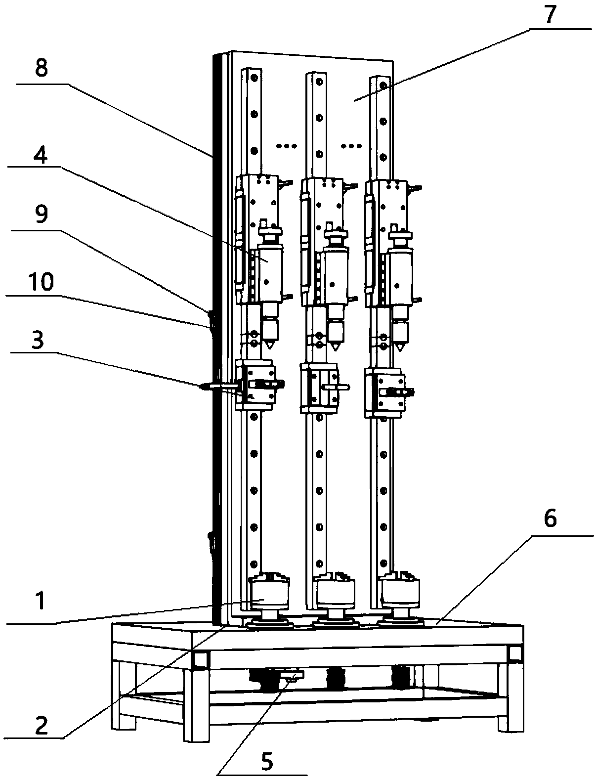
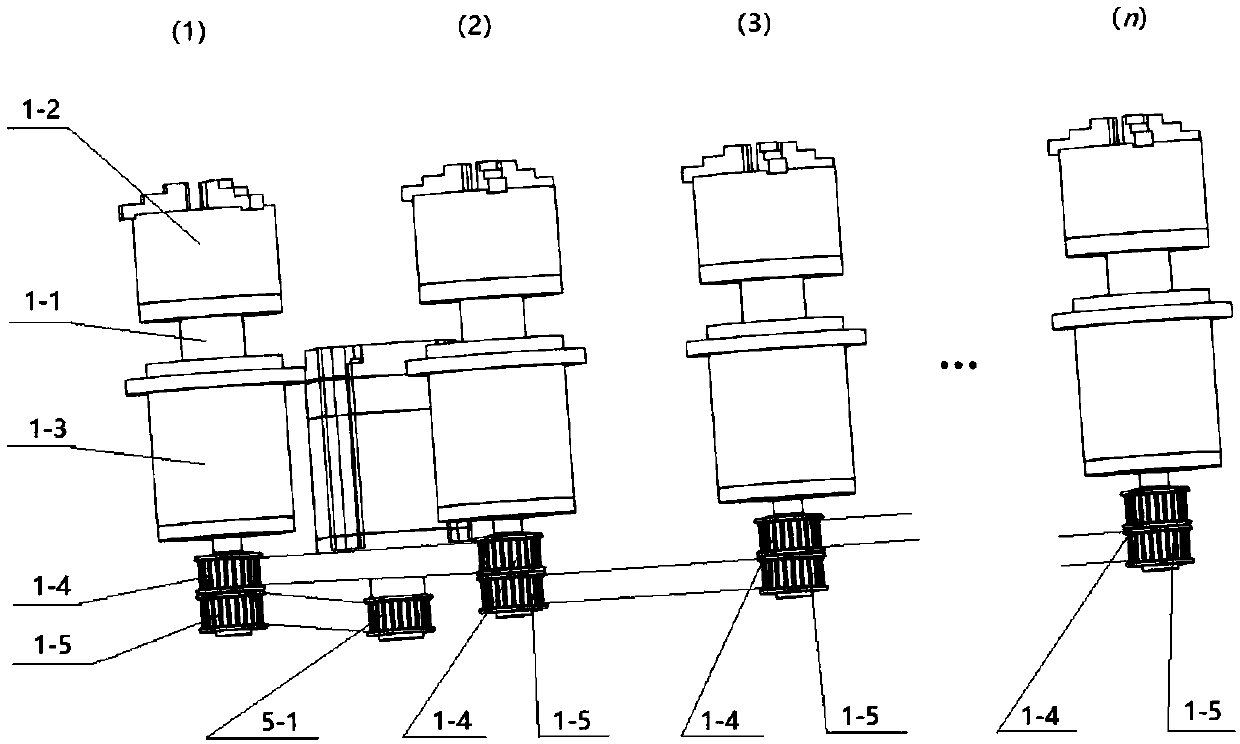
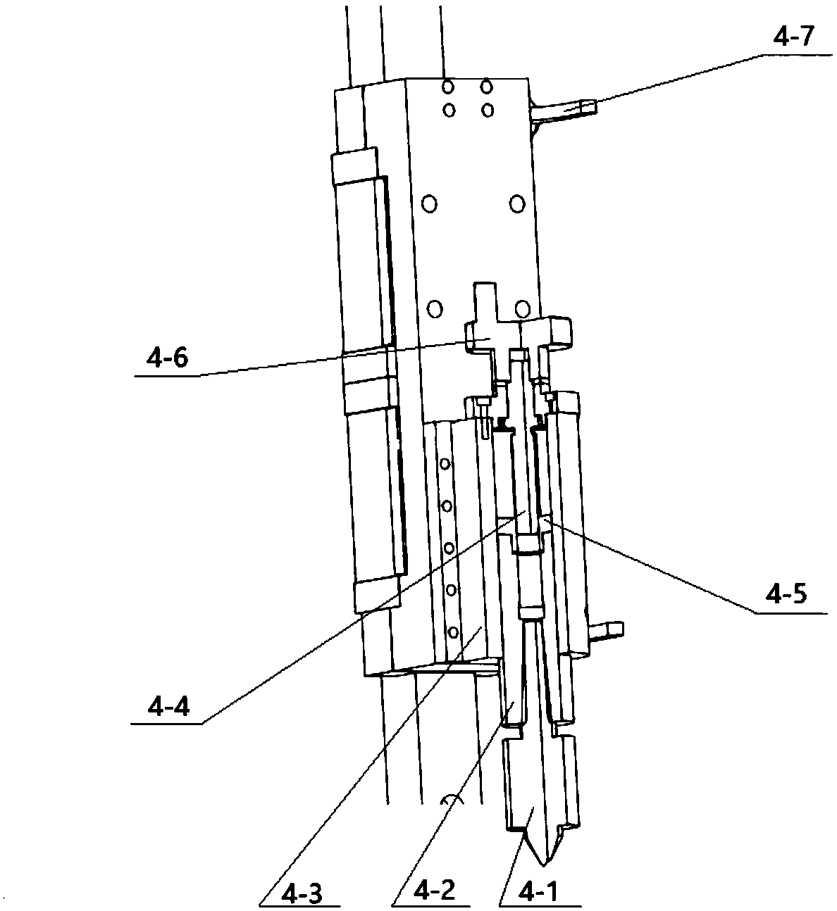
[0038] In this embodiment, n=3, m=2. combine Image 6 , the present invention is suitable for a running-in device for miniature ball screw pairs, including a headstock group, a bed 2, a workbench group, a tailstock group, and a motor 5; the bed 2 includes a base 6 and a panel 7, and the panel 7 Vertically arranged on the upper surface of the base 6; the head frame group includes 3 groups of head frames 1, the workbench group includes 3 groups of workbenches 3, and the tail frame group includes 3 groups of tail frames 4; one side of the panel 7 is provided with 3 A set of guide rails with a first slide block and a second slide block perpendicular to the upper surface of the base 6, each set of guide rails is coaxially arranged with the corresponding tailstock 4 and workbench 3 from the end far away from the base 6, and the tailstock 4. The workbench 3 is set on the first slider and the second slider respectively; the headstock 1 and the tailstock 4 on each set of guide rails, ...


PUM


Abstract

The invention discloses a running-in device suitable for a micro-small ball screw pair and a running method thereof. The running-in device comprises n sets of headstocks, a lathe bed, n sets of worktables, n sets of tailstocks, and a motor. Wherein the lathe bed comprises a base and a panel, and the panel is vertically arranged on the upper surface of the base; n sets of guide rails with a first slider and a second slider vertical to the upper surface of the base are arranged on one side of the panel; on each set of guide rails, the corresponding tailstock and worktable are coaxially arrangedfrom the end far from the base; and the tailstock and the workbench are respectively arranged on the first slider and the second slider; the headstock and the tailstock and the worktable on each set of guide rails are coaxially arranged on the upper surface of the base; the motor for driving the movement of the headstocks is arranged on the side of the base, and a motor timing pulley is arranged on the motor. According to the running-in device suitable for the micro-small ball screw pair and the running method thereof, the running-in of a plurality of micro-small ball screw pairs can be realized at the same time, the efficiency of the running-in is high, a vertical structure is adopted, the structure is simple, the coaxiality error of the headstocks and the tailstocks, and running-in screwdeflection can be reduced.

Description

technical field [0001] The invention belongs to the field of ball screw running-in, in particular to a running-in device and a running-in method suitable for miniature ball screw pairs. Background technique [0002] The running-in of the ball screw pair is a necessary process for the screw. This process can eliminate the deformation after processing or heat treatment, and can further improve the contact accuracy of the ball screw pair and reduce noise. For ball screw pairs with high speed and heavy load, running-in is even more important. The running-in device of the ball screw pair at home and abroad is relatively mature. At present, the running-in device of the medium and large ball screw pair is relatively complete, but there are still restrictions on the running-in device of the micro-small screw. The running-in and clamping of the micro-sized screw is difficult and requires specific tooling. At present, manual running-in is generally used for the running-in of the micr...

Claims


Application Information

Patent Timeline
Patent Type & Authority Applications(China)
IPC IPC(8): G01M13/02
CPCG01M13/02
Inventor 欧屹魏一凡韩军
Owner NANJING UNIV OF SCI & TECH
Why Eureka
Try Eureka