
Display panel and display device

A display panel and encapsulation layer technology, which is applied to semiconductor devices, electrical components, circuits, etc., can solve problems such as increased stress, black spots, bright spots, and colorful spots in the display area, and stress surges on the display screen.

Inactive Publication Date: 2018-12-28
KUNSHAN GO VISIONOX OPTO ELECTRONICS CO LTD
View PDF5 Cites 14 Cited by
  • Summary
  • Abstract
  • Description
  • Claims
  • Application Information

AI Technical Summary

Problems solved by technology

[0003] After the organic light-emitting diode display is manufactured, it is usually necessary to conduct a series of reliability tests on the display screen. Usually, the ball drop test is used to test the impact resistance of the screen. The phenomenon of stress surge may cause display abnormalities, especially for flexible screens. When it is subjected to an instantaneous impact, due to the absence of a hard protective layer, the stress increases sharply, which is more likely to cause black spots, bright spots, and colorful spots in the display area. defect

Method used


Image

  • Display panel and display device
  • Display panel and display device
  • Display panel and display device

Examples


Embodiment Construction

[0021] In order to make the purpose, technical solution and advantages of the present application clearer, the present application will be further described in detail below in conjunction with the accompanying drawings and embodiments. It should be understood that the specific embodiments described here are only used to explain the present application, and are not intended to limit the present application.

[0022] It should be noted that when an element is referred to as being “disposed on” another element, it may be directly on the other element or there may also be an intervening element. When an element is referred to as being "connected to" another element, it can be directly connected to the other element or intervening elements may also be present. The terms "vertical," "horizontal," "left," "right," and similar expressions are used herein for purposes of illustration only and are not intended to represent the only embodiments.

[0023] Unless otherwise defined, all te...


PUM


Abstract

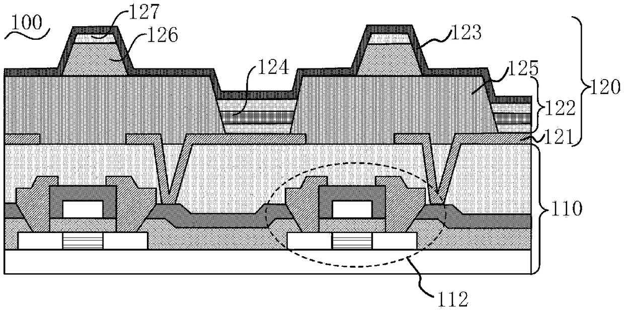
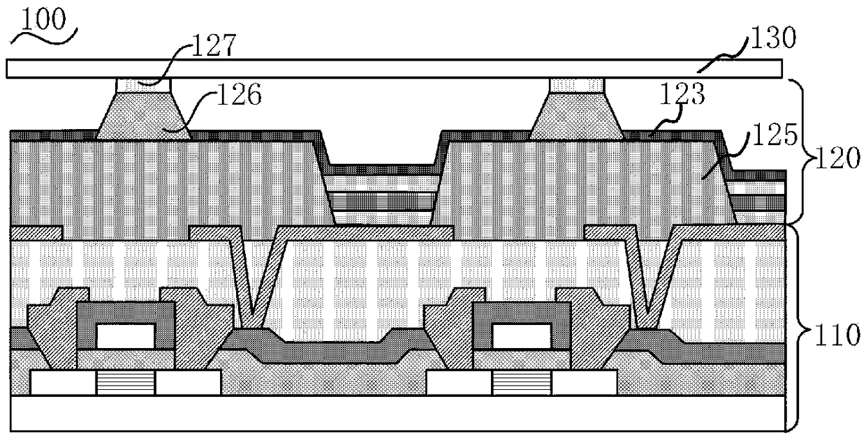
The invention relates to a display panel and a display device. The display panel includes an array substrate and a light emitting structure arranged on the array substrate. The light emitting structure includes a first electrode, an organic light emitting layer formed on the first electrode, and a second electrode. The organic light emitting layer includes pixels and a pixel defining layer arranged between adjacent pixels. The light emitting structure further comprises a plurality of support columns and a plurality of buffer structures. Each support column is independently disposed on a surface of the pixel defining layer facing the second electrode, and each buffer structure is correspondingly disposed on a surface of the support column remote from the pixel defining layer. The display panel and the display device can effectively reduce the damage to the luminescent structure layer on the supporting pillar when the display panel is subjected to external impact, can effectively disperse and absorb the instantaneous increased stress on the display panel, increase the impact resistance of the screen, achieve the purpose of protecting the film layer structure under the impact of external force and improve the stress diffusion ability.

Description

technical field [0001] The invention relates to the field of display devices, in particular to a display panel and a display device. Background technique [0002] Organic light-emitting diode (Organic Light-Emitting Diode, OLED) display, also known as organic electroluminescent display, is a new type of flat panel display device, due to its simple preparation process, low cost, low power consumption, high luminance, It has the advantages of light and thin volume, fast response speed, and easy realization of color display, large-screen display, and flexible display, etc., and has broad application prospects. [0003] After the organic light-emitting diode display is manufactured, it is usually necessary to conduct a series of reliability tests on the display screen. Usually, the ball drop test is used to test the impact resistance of the screen. The phenomenon of stress surge may cause display abnormalities, especially for flexible screens. When it is subjected to an instant...

Claims


Application Information

Patent Timeline
IPC IPC(8): H01L27/32
CPCH10K59/121H10K59/00H10K59/122
Inventor 雷博琳张德强
Owner KUNSHAN GO VISIONOX OPTO ELECTRONICS CO LTD
Learn More