A dual-polarization radiating element and an array antenna provided with the dual-polarization radiating element

A radiating element and array antenna technology, which is applied to a separately powered antenna array, radiating element structure, antenna, etc., can solve problems such as influence, unfavorable antenna performance, and the inability of antenna radiating elements to meet the requirements, so as to reduce process complexity and facilitate the The effect of integrated design, improved data capacity and spectral efficiency

Pending Publication Date: 2018-12-28
JIANGSU HENGXIN TECH CO LTD +1
View PDF0 Cites 8 Cited by
  • Summary
  • Abstract
  • Description
  • Claims
  • Application Information

AI Technical Summary

Problems solved by technology

[0004] When a large-scale array antenna is actually working, the coupling between the array elements always exists, which will have a very adverse eff

Method used


Image

  • A dual-polarization radiating element and an array antenna provided with the dual-polarization radiating element
  • A dual-polarization radiating element and an array antenna provided with the dual-polarization radiating element
  • A dual-polarization radiating element and an array antenna provided with the dual-polarization radiating element

Examples


Example Embodiment

[0023] Embodiment one:

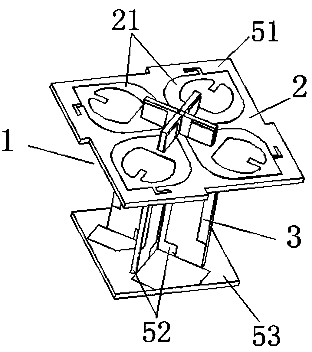
[0024] See figure 1 , this embodiment discloses a dual-polarized radiation unit, the dual-polarized radiation unit 1 includes a radiation device 2, a balun feeding device 3, and a radiation unit base 53, and the radiation device 2 passes through the balun feeding device 3 is supported on the radiating unit base 53, one end of the balun feeding device 3 is connected to the radiating device 2, and the other end of the balun feeding device 3 is connected to the radiating unit base 53, and the radiating device 2 The balun feeding device 3 is arranged on the base 53 of the radiation unit;

[0025] The balun feeding device 3 includes two second PCB substrates 52 arranged in a cross, each of the second PCB substrates 52 is provided with a balun device and a feeding device, and the balun device is arranged on The first microstrip line on one side of the second PCB substrate 52, the feeding device is a second microstrip line arranged on the other side of the ...

Example Embodiment

[0032] Embodiment two:

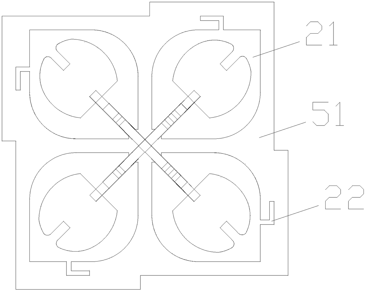
[0033] like figure 2 As shown, the effective length of the decoupling circuit 22 in Embodiment 1 is set to 0.035 wavelengths, the wavelength is equal to the transmission speed of the electromagnetic wave divided by the frequency, and the transmission speed of the electromagnetic wave is equal to 3*10 ^8 m / s, the frequency is 3300-3800MHz, preferably 3500MHz.

Example Embodiment

[0034] Embodiment three:

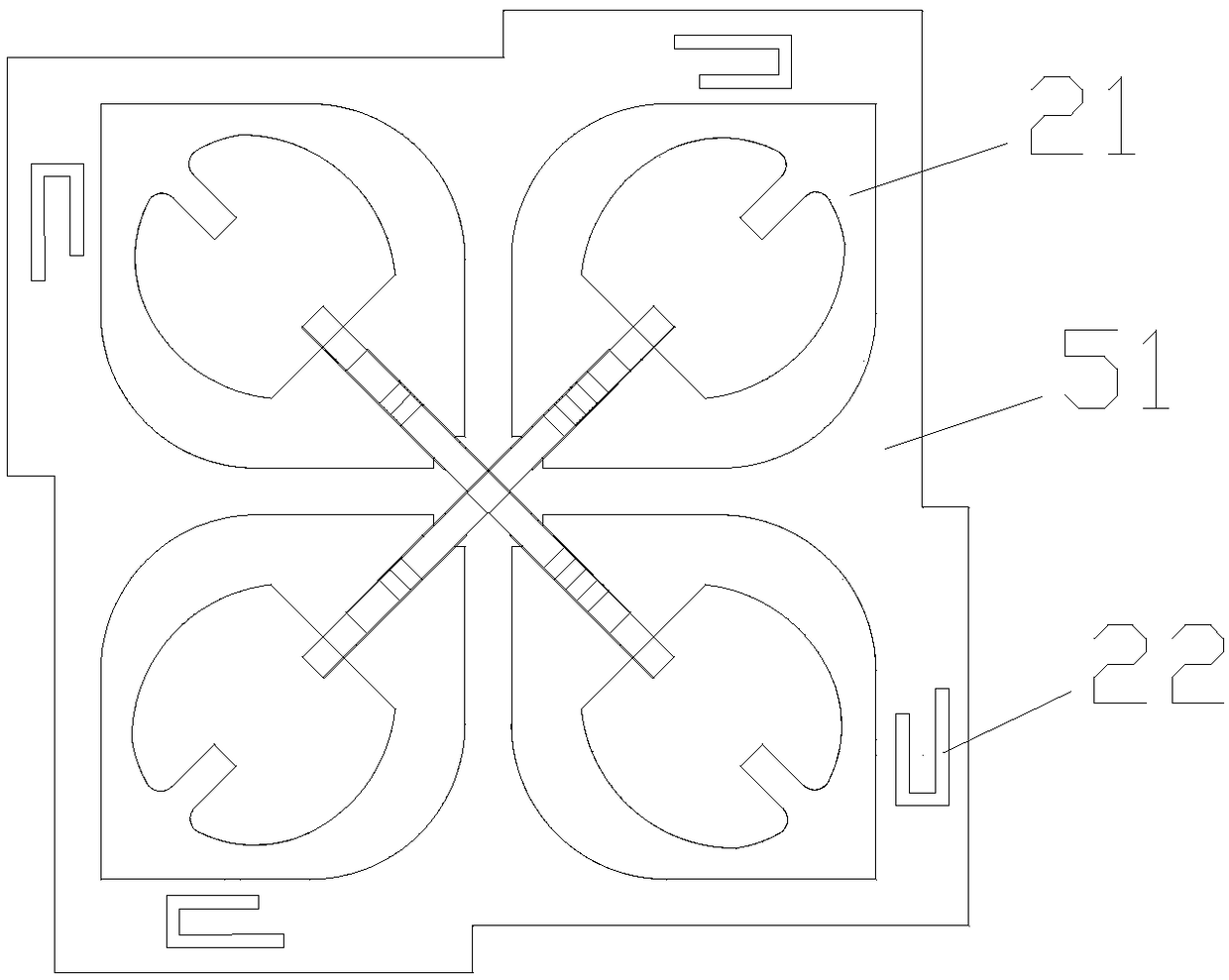
[0035] like image 3 As shown, on the basis of Embodiment 1, the array arm 21 is connected to the decoupling circuit 22 in a coupling manner, and the effective length of the decoupling circuit 22 is set to 0.04 wavelengths. The decoupling circuit 22 is preferably Set in a "U" shape, the effective length of the "U"-shaped decoupling circuit 22 is the sum of the sum of the three sides, and the coupling distance between the decoupling circuit 22 and the array arm 21 is smaller than that of the decoupling circuit effective length.


PUM

PropertyMeasurementUnit
Resistanceaaaaaaaaaa

Abstract

The invention discloses a dual-polarization radiating unit and an array antenna provided with the dual-polarization radiating unit, the main technical problem to be solved is the problem of mutual coupling between arrays in the prior art. The dual-polarization radiating element includes a radiation device, which comprises array arms arranged symmetrically on a first PCB substrate, and the array arms are connected with a decoupling circuit by a direct feed mode or a coupling mode. The technical scheme that the effective length of the decoupling circuit is 0.02 to 0.1 wavelength solves the problem well and can be used for an array antenna.

Description

technical field [0001] The invention relates to a dual-polarization radiation unit and an array antenna with the dual-polarization radiation unit. Background technique [0002] With the development of the mobile Internet and the Internet of Things, the network speed, network capacity, number of terminal connections and air interface delay of the 4G mobile communication system can no longer meet the needs of the market and technology evolution. In the future, wider bandwidth, higher speed, and lower power consumption are required. 5G mobile communication technology with low latency and shorter delay will face huge challenges for base station antennas. Traditional base station antennas can no longer meet the needs of 5G systems. [0003] As one of the key technologies of 5G, large-scale antenna technology can well solve the shortcomings of 4G technology, by arranging dozens or hundreds of antenna arrays at the base station instead of just a few antennas , to radiate signals t...

Claims


Application Information

Patent Timeline
IPC IPC(8): H01Q1/38H01Q1/52H01Q1/50H01Q19/10H01Q21/06
CPCH01Q1/38H01Q1/50H01Q1/523H01Q19/104H01Q21/061
Inventor 姜盼梁启迪王会霞钱军
Owner JIANGSU HENGXIN TECH CO LTD
Why Eureka
Try Eureka