
Special-shaped part automatic plug-in soldering robot and control method thereof

A soldering robot and automatic plug-in technology, applied in manufacturing tools, welding equipment, auxiliary welding equipment, etc., can solve the problems of multiple workers, increased labor costs, and reduced equipment cost efficiency.

Pending Publication Date: 2019-01-01
锐驰机器人(深圳)有限公司
View PDF0 Cites 3 Cited by
  • Summary
  • Abstract
  • Description
  • Claims
  • Application Information

AI Technical Summary

Problems solved by technology

Even if many companies use independent automatic plug-in machines and soldering machines, it is still necessary to manually transfer the processed workpieces from the plug-in machine to the soldering machine for operation, which leads to a large number of workers and increases labor costs.
At the same time, the plug-in machine and the soldering machine are independent systems, and the position offset after the transfer of the workpiece requires secondary positioning during soldering, which also brings about an increase in equipment costs and a decrease in efficiency
[0003] Therefore, in order to solve the above problems, in the prior art, a six-axis robot is used for plug-in and soldering. Although it can solve the labor cost problem between plug-in and solder to a certain extent, this technology uses a six-axis robot to increase the equipment cost virtually.

Method used


Image

  • Special-shaped part automatic plug-in soldering robot and control method thereof
  • Special-shaped part automatic plug-in soldering robot and control method thereof
  • Special-shaped part automatic plug-in soldering robot and control method thereof

Examples


Embodiment Construction

[0035] The following will clearly and completely describe the technical solutions in the embodiments of the present invention with reference to the accompanying drawings in the embodiments of the present invention. Obviously, the described embodiments are only part of the embodiments of the present invention, not all of them. Based on the embodiments of the present invention, all other embodiments obtained by persons of ordinary skill in the art without creative efforts fall within the protection scope of the present invention.

[0036] It should be noted that all directional indications (such as up, down, left, right, front, back...) in the embodiments of the present invention are only used to explain the relationship between the components in a certain posture (as shown in the accompanying drawings). Relative positional relationship, movement conditions, etc., if the specific posture changes, the directional indication will also change accordingly.

[0037] In addition, the ...


PUM


Abstract

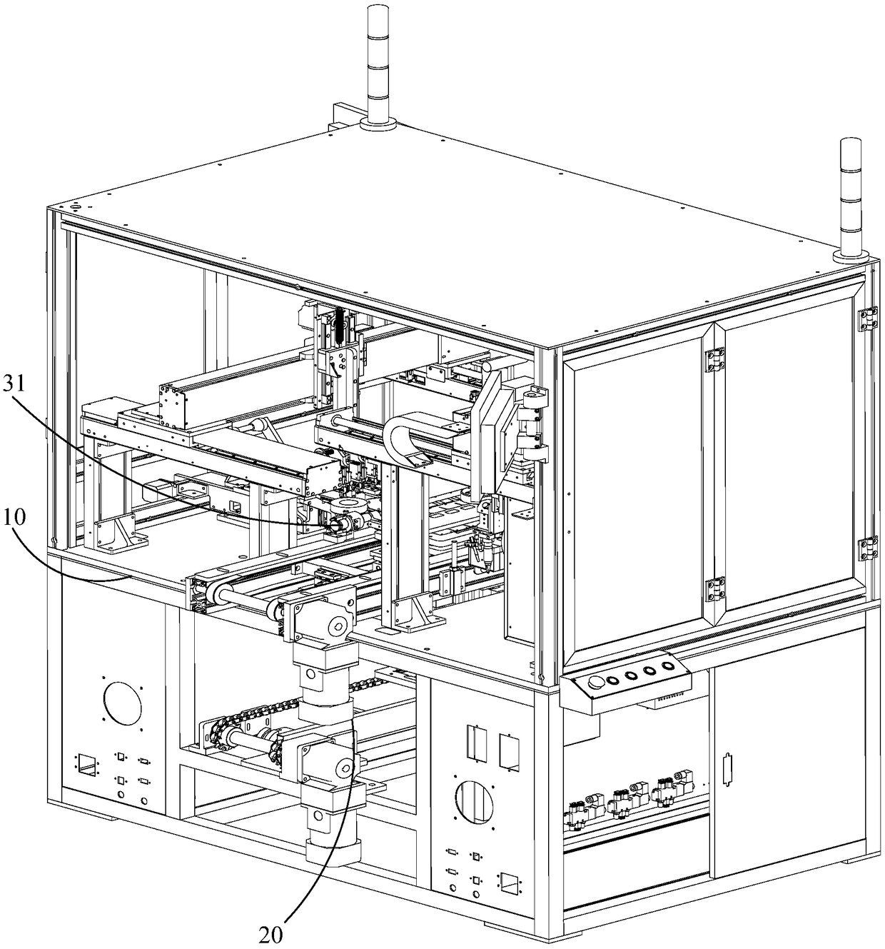
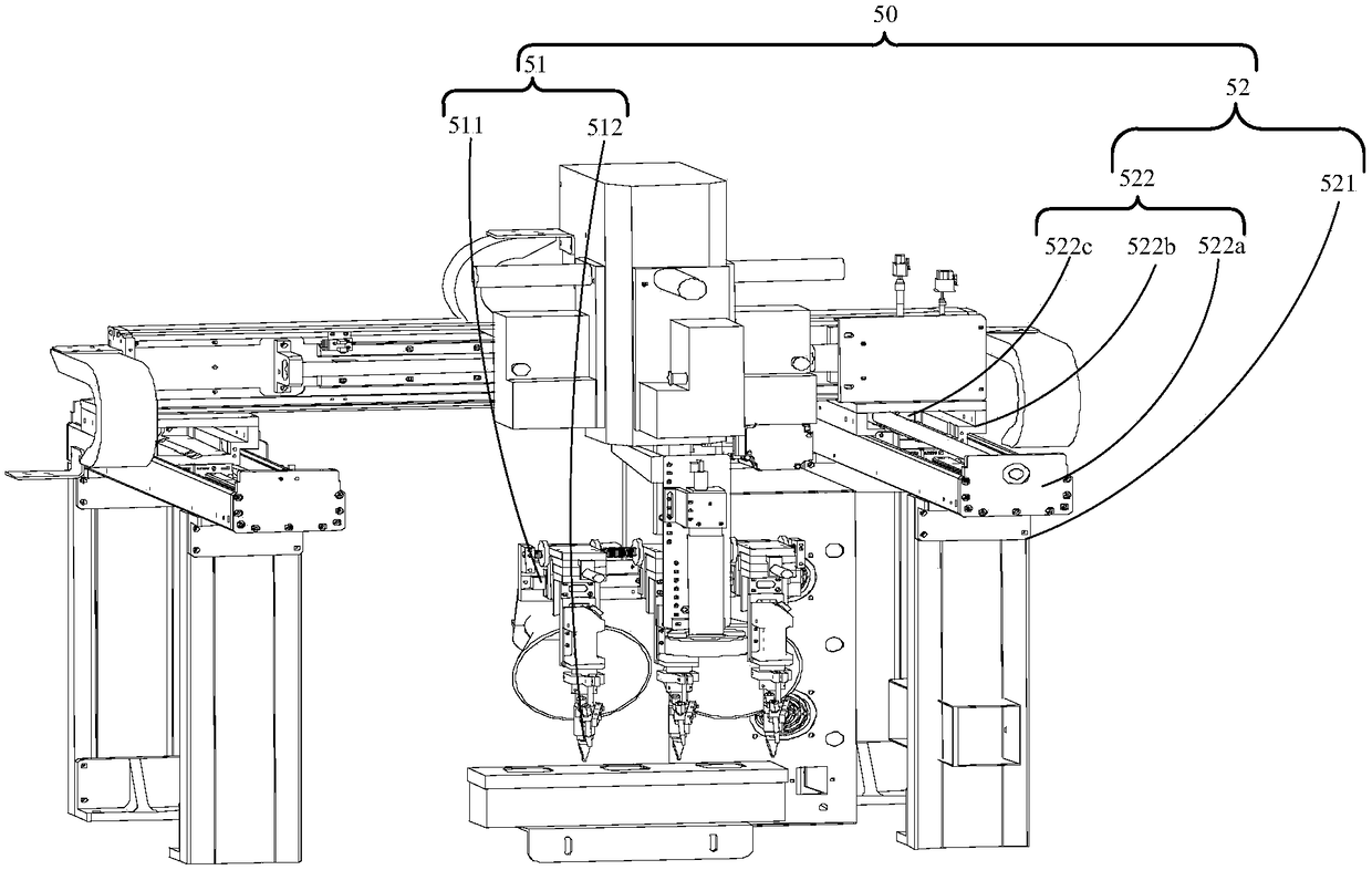
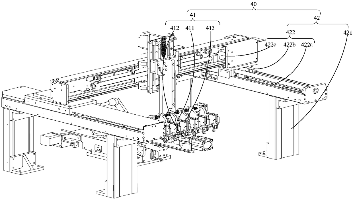
The invention discloses a special-shaped part automatic plug-in soldering robot and a control method thereof. The special-shaped part automatic plug-in soldering robot comprises a rack, a transmissiondevice, a material supply device, a plug-in device and a soldering device; a worktable is arranged on the rack, the transmission device is arranged on the worktable, and is used for conveying a to-be-machined circuit board to the machining position, the material supply device is arranged on the worktable, and used for conveying a special-shaped part to be machined to the loading position, the plug-in device comprises a clamping assembly and a plug-in moving assembly driving the clamping assembly to move, the clamping assembly is arranged on the plug-in moving assembly, and the plug-in movingassembly is arranged on the worktable; the soldering device comprises a soldering assembly and a soldering moving assembly for driving the soldering assembly to move, the soldering assembly is arranged on the soldering moving assembly, and the soldering moving assembly is arranged on the worktable. Manual cost is reduced, and production efficiency is improved.

Description

technical field [0001] The invention relates to the technical field of plug-in soldering, in particular to an automatic plug-in soldering robot for special-shaped parts and a control method thereof. Background technique [0002] At present, the plug-in machine and soldering machine have been widely used in the fields of computer, communication electronics, automotive electronics and other electronic product manufacturing. The automatic plug-in machine and soldering machine are two kinds of equipment that work independently. Even if many companies use independent automatic plug-in machines and soldering machines, they still need to manually transfer the processed workpieces from the plug-in machine to the soldering machine for operation, which leads to a large number of workers and increases labor costs. At the same time, the plug-in machine and the soldering machine are independent systems, and the position offset after the transfer of the workpiece requires secondary positi...

Claims


Application Information

Patent Timeline
IPC IPC(8): B23K3/00B23K3/08B23K37/02
CPCB23K3/00B23K3/08B23K37/0252
Inventor 唐龙胡勇
Owner 锐驰机器人(深圳)有限公司
Learn More