Four-axis stamping manipulator

A manipulator and manipulator technology, applied in the field of four-axis stamping manipulators, can solve the problems of inability to realize rational utilization of space resources, cumbersome screw fixation, cumbersome screw replacement, etc. Effect

Pending Publication Date: 2019-01-01
HANGZHOU KINGNET ELECTROMECHANICAL
View PDF7 Cites 0 Cited by
  • Summary
  • Abstract
  • Description
  • Claims
  • Application Information

AI Technical Summary

Problems solved by technology

[0003] At present, the manipulators on the market are two upper and lower profiles, one of which is connected to the grab material gripper at the end of the profile, and the other profile is fixed or movably connected to the frame. When in use, the gripper is driven by a motor. The profile of the hand moves back and forth, and the motor drives the profile through the screw rod at present. The motor drives the screw to rotate forward and reverse, and then drives the profile to move forward and backward. It has the advantages of good transmission effect and rapid power output. , but the screw rod is used for transmission. In order to ensure that the profile with the gripper can be stably driven back and forth during the transmission process, the screw rod has a large volume and occupies a large space, resulting in a large profile. As a result, the volume of the entire device increases, and it takes up a lot of space in the process of workshop transfer, making it impossible to achieve a reasonable use of space resources.
[0004] And because the screw rod is a metal rod, on the one hand, it is more complicated to fix the screw rod, and the operation is difficult; on the other hand, the screw rod is made of metal, which requires high cost and increases the cost of the whole equipment; During the working process of the rod, it is cumbersome to replace the screw rod after wear and tear, and the cost of replacement and maintenance is also high

Method used


Image

  • Four-axis stamping manipulator
  • Four-axis stamping manipulator
  • Four-axis stamping manipulator

Examples


Embodiment Construction

[0034] In order to enable those skilled in the art to better understand the solutions of the present invention, the technical solutions in the embodiments of the present invention will be clearly and completely described below in conjunction with the drawings in the embodiments of the present invention.

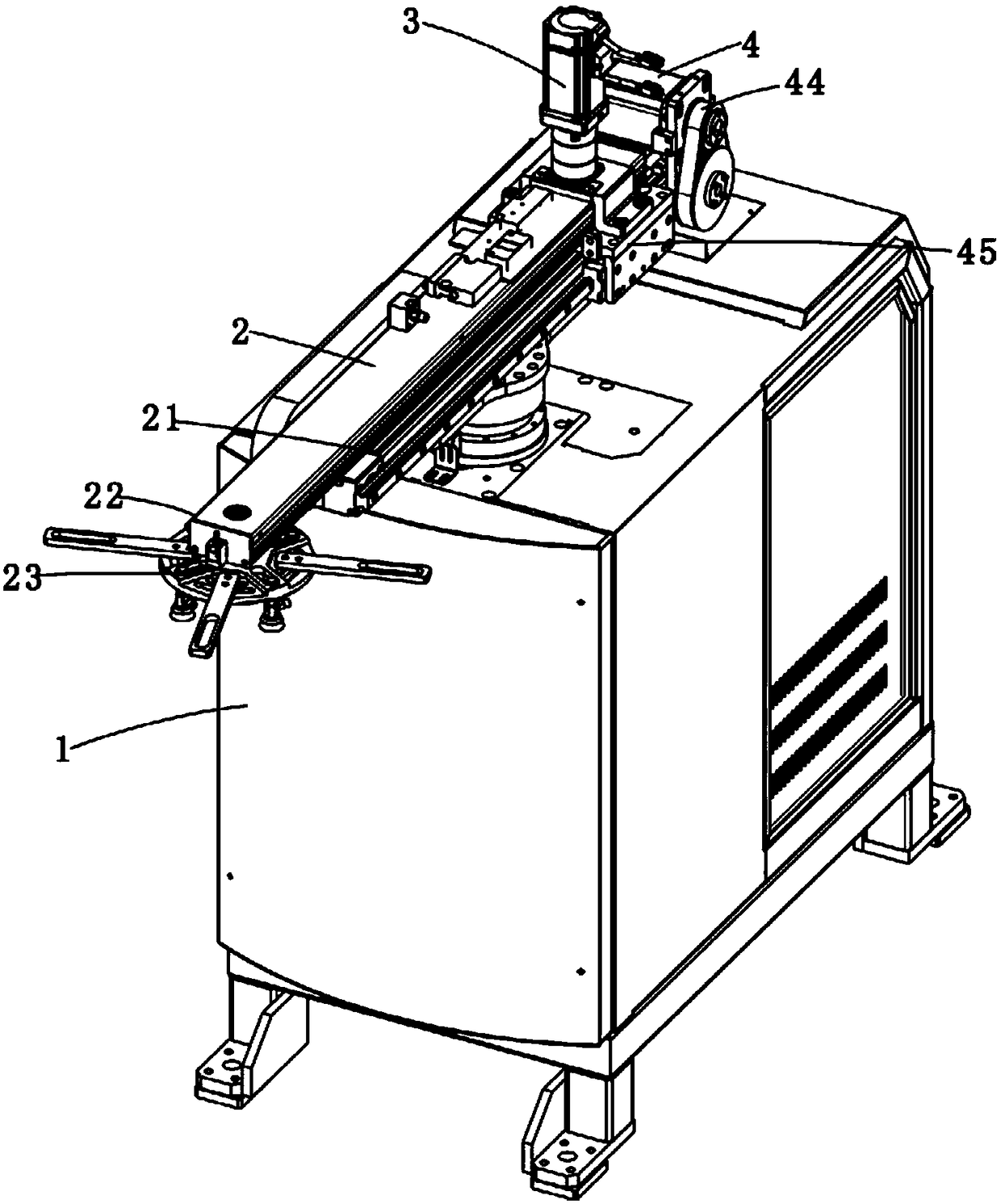
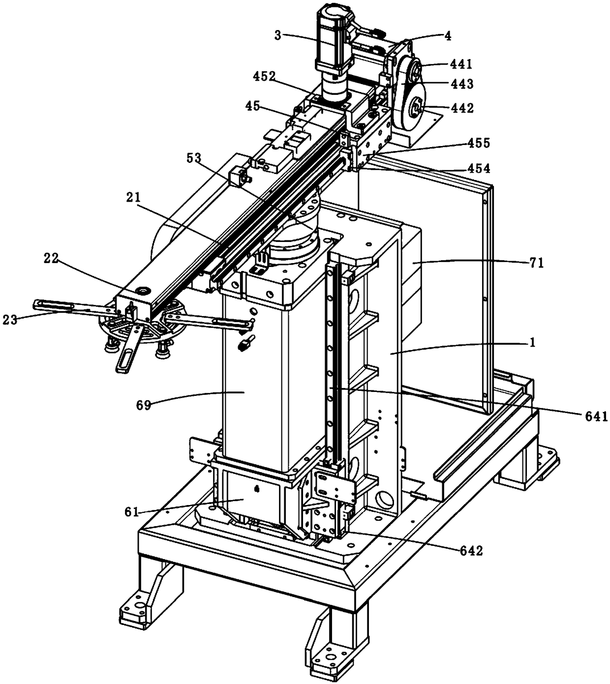
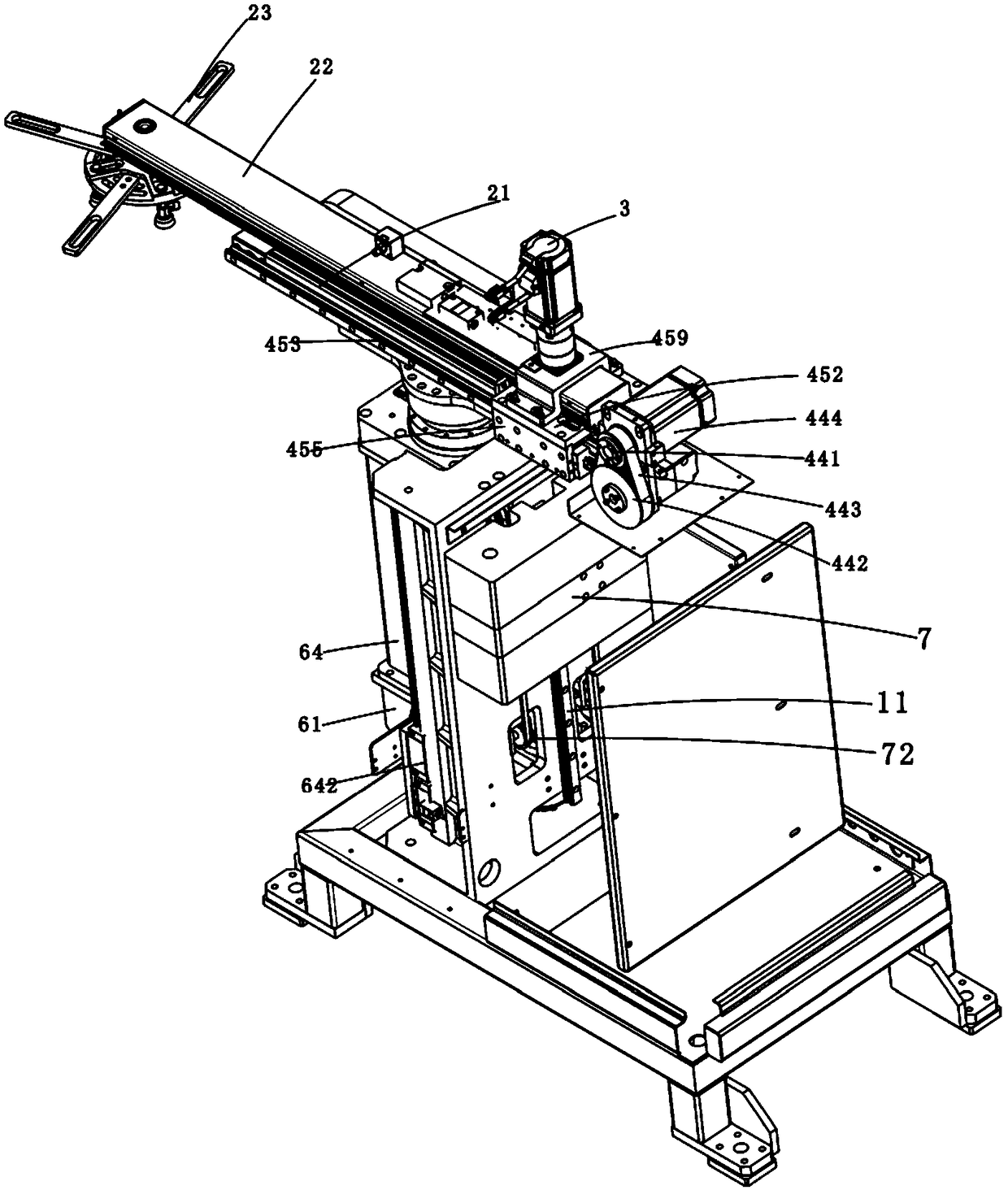
[0035] Such as Figure 1-11 As shown, a four-axis stamping manipulator includes a frame 1, a grabbing device 2, a first driving device 3, a second driving device 4, a third driving device 5, a fourth driving device 6 and a counterweight device 7. The frame 1 is a metal frame; the grabbing device 2 includes a first mechanical arm 21, a second mechanical arm 22 and a retrieving part 23 for grabbing materials, wherein the first mechanical arm 21 is horizontally arranged aluminum profile, the second mechanical arm 22 is also an aluminum profile; the third driving device 5 is arranged on the frame 1, and the first mechanical arm 21 is connected with the third driving device 5, so ...


PUM


Abstract

The invention discloses a four-axis stamping manipulator which comprises a rack, a grabbing device, a first drive device, a second drive device and a third drive device. The grabbing device is used for grabbing materials and comprises a first mechanical arm, a second mechanical arm capable of moving front and back along the length direction of the first mechanical arm, and a material taking part arranged on the second mechanical arm; the first drive device is used for driving the material taking part to rotate on the second mechanical arm; the second drive device is used for driving the firstmechanical arm to act front and back relative to the second mechanical arm through a conveyor belt; and the third drive device is arranged on the rack and is used for driving the grabbing device to rotate relative to the rack. According to the four-axis stamping manipulator provided by the invention, the second drive device drives the second mechanical arm to act front and back through the conveyor belt, the volume is small, the weight is light, and the volume of the whole manipulator is reduced, so that the volume of the whole equipment is small, less space is occupied, and reasonable arrangement of the space of the whole workshop can be improved.

Description

technical field [0001] The invention belongs to the technical field of material processing, and in particular relates to a four-axis stamping manipulator. Background technique [0002] With the continuous advancement of science and technology, when processing materials, most of the materials are grasped by manipulators instead of manual pick-and-place materials, because the manipulators can continuously grasp and put down materials, and can also It works for a long time, so compared with manual labor, it has the advantages of low cost and high work efficiency. [0003] At present, the manipulators on the market are two upper and lower profiles, one of which is connected to the grab material gripper at the end of the profile, and the other profile is fixed or movably connected to the frame. When in use, the gripper is driven by a motor. The profile of the hand moves back and forth, and the motor drives the profile through the screw rod at present. The motor drives the screw ...

Claims


Application Information

Patent Timeline
Patent Type & Authority Applications(China)
IPC IPC(8): B25J9/12B25J15/06B25J19/00B21D43/10
CPCB21D43/105B25J9/104B25J9/109B25J9/12B25J15/0633B25J19/002
Inventor 潘利锋
Owner HANGZHOU KINGNET ELECTROMECHANICAL
Why Eureka
Try Eureka