Pedal-type shaft transmission mechanism which adopts a non-circular bevel gear

A non-conical gear and non-conical technology, applied in the direction of wheel transmission, rotary transmission, vehicle gearbox, etc., can solve the problems of unconformity with ergonomic mechanical characteristics, chain shedding and slack, poor transmission stability, etc., and achieve improvement The effect of cycling experience, reducing discomfort, and smooth transmission

Inactive Publication Date: 2019-01-01
HEFEI UNIV OF TECH
View PDF4 Cites 0 Cited by
  • Summary
  • Abstract
  • Description
  • Claims
  • Application Information

AI Technical Summary

Problems solved by technology

However, chain drive bicycles also have many disadvantages, such as poor transmission stability, small torque, chain shedding and slack, loud driving noise, and oil pollution problems; Safety, maintenance-free, stable transmission, clean, comfortable advantages, has been favored by many
[0003] Existing shaft-driven bicycles generally use bevel gears to transmit power from the pedals to the rear wheels of the bicycle. This transmission method achieves constant speed ratio transmission during the entire cycle of the pedals, which does not conform to ergonomic mechanical characteristics.

Method used


Image

  • Pedal-type shaft transmission mechanism which adopts a non-circular bevel gear
  • Pedal-type shaft transmission mechanism which adopts a non-circular bevel gear
  • Pedal-type shaft transmission mechanism which adopts a non-circular bevel gear

Examples


Embodiment 1

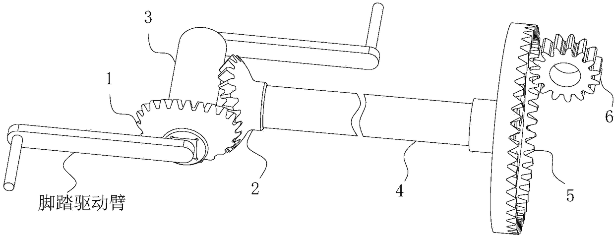
[0038] see figure 1 , a pedal-type shaft transmission mechanism using non-conical gears includes a non-conical gear pair, a pedal shaft 3, a power transmission shaft 4 and a face gear pair.

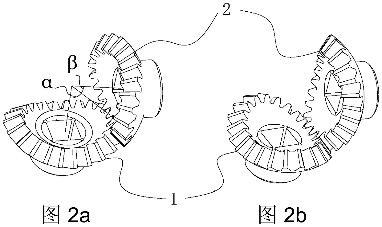
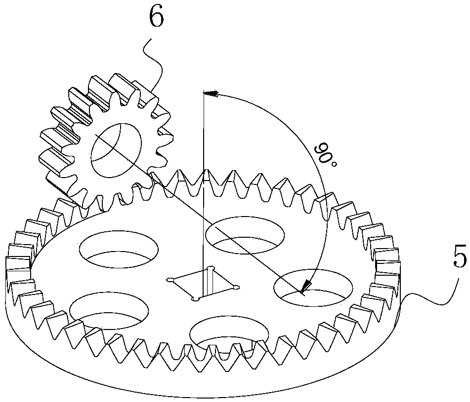
[0039] see figure 2 a and figure 2 b. The non-conical gear pair includes non-conical driving gear 1 and non-conical driven gear 2. The non-conical driving gear and non-conical driven gear have the same structure, which is an oval bevel gear pair with a long diameter part and a short diameter part. The pitch cone surface of the oval bevel gear pair is non-conical, the sum of the maximum pitch cone angle α of the long diameter part and the minimum pitch cone angle β of the short diameter part is 90°, the maximum pitch cone angle α of the long diameter part and the short diameter part The minimum pitch angle β ratio of the diameter part is 1.35. see image 3 , the shaft angle of the non-conical gear pair is 90 degrees.

[0040] The non-conical driving gear 1 is fixedly mounted on one...


PUM


Abstract

The invention relates to a pedal-type shaft transmission mechanism which adopts a non-circular bevel gear. The pedal-type shaft transmission mechanism includes a non-bevel gear pair, a pedal shaft, apower shaft and a face gear pair; a non-circular bevel gear pair is an oval bevel gear pair having a long diameter portion and a short diameter portion. During working, the non-bevel gear pair transmits the power to the face gear pair through the power transmission shaft to realize the pedal drive. When the foot pedal is in a state nearly perpendicular to the ground, the short diameter portion ofthe non-conical driving wheel engages with the long diameter portion of the non-conical driven wheel; when the foot pedal is in a state nearly parallel to the ground, the long diameter portion of thenon-conical driving wheel meshes with the short diameter portion of the non-conical driven wheel. When the foot pedal is in the vicinity of the dead point, the invention can make the power transmission part have a smaller speed increase ratio, and when the foot pedal is in the power generating area, the power transmission part has a larger speed increase ratio, so as to improve the cycling experience of the rider and reduce the discomfort feeling in the cycling process for a long time.

Description

technical field [0001] The invention belongs to the field of bicycle manufacturing, in particular to the field of shaft-driven bicycle manufacturing, and relates to a pedal-type shaft transmission mechanism using non-conical gears. Background technique [0002] The current transmission modes of bicycles include chain transmission, synchronous toothed belt transmission, shaft transmission and other transmission modes, among which chain transmission has become the mainstream mode of bicycle transmission due to its advantages of low cost, light weight and convenient maintenance. At the beginning of the advent of chain-driven bicycles, some designers proposed the use of an elliptical sprocket transmission method to realize the acceleration of the rider when the pedal is from the up and down position to the horizontal position, and decelerate during the process from the horizontal position to the up and down position. However, chain drive bicycles also have many disadvantages, su...

Claims


Application Information

Patent Timeline
Patent Type & Authority Applications(China)
IPC IPC(8): B62M11/10
CPCB62M11/10B62M17/00
Inventor 韩江李大柱夏链田晓青
Owner HEFEI UNIV OF TECH
Why Eureka
Try Eureka