Transferring and loading mechanism
A transfer and suction cup technology, applied in conveyors, conveyor objects, furnaces, etc., can solve the problems of increased production costs, lack of adjustment functions, etc., and achieve the effect of improving versatility
- Summary
- Abstract
- Description
- Claims
- Application Information
AI Technical Summary
Problems solved by technology
Method used
Image

Examples
Embodiment 1
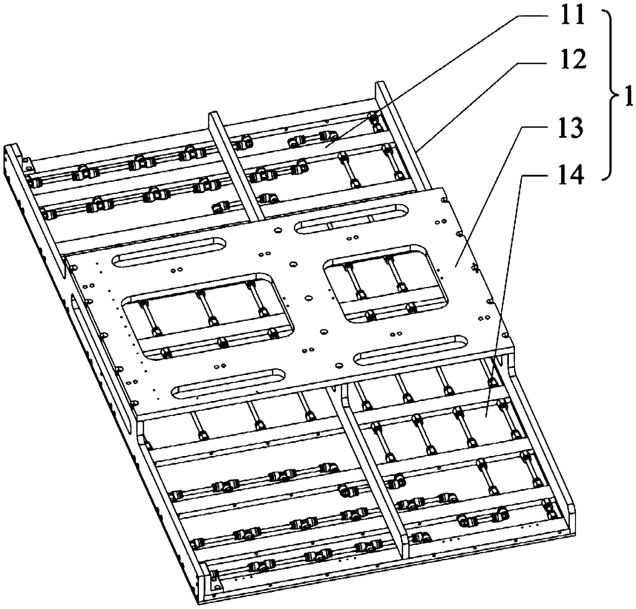
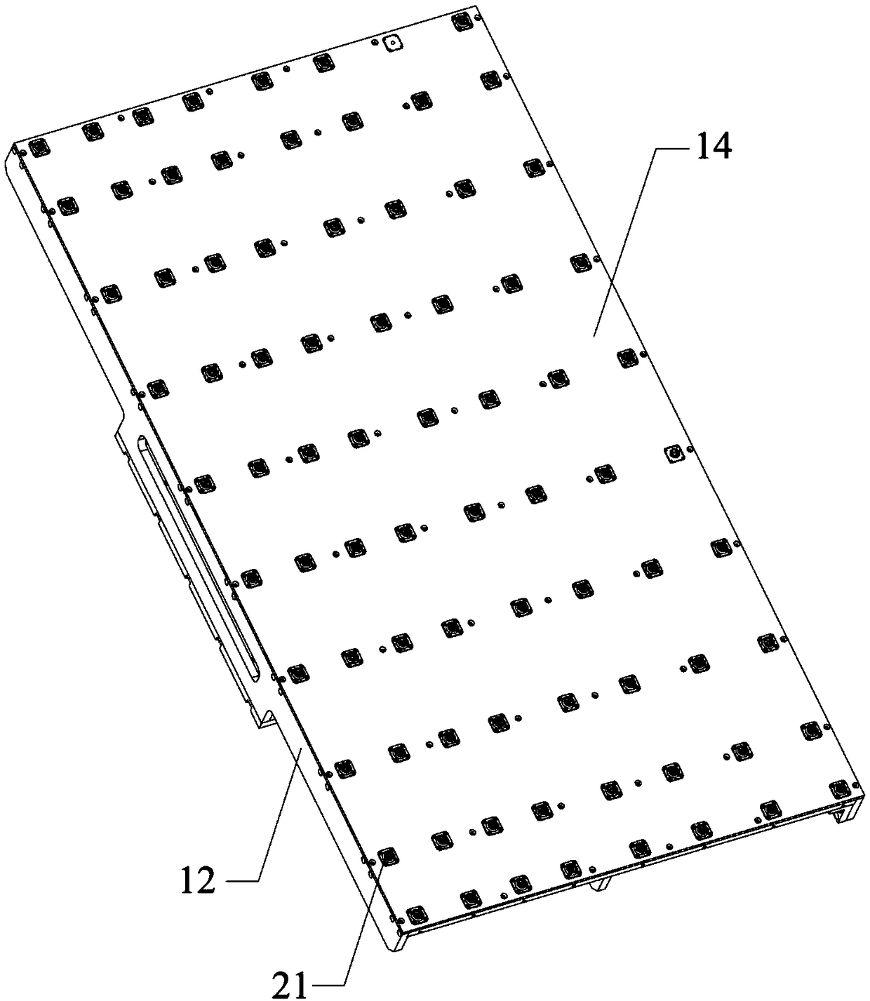
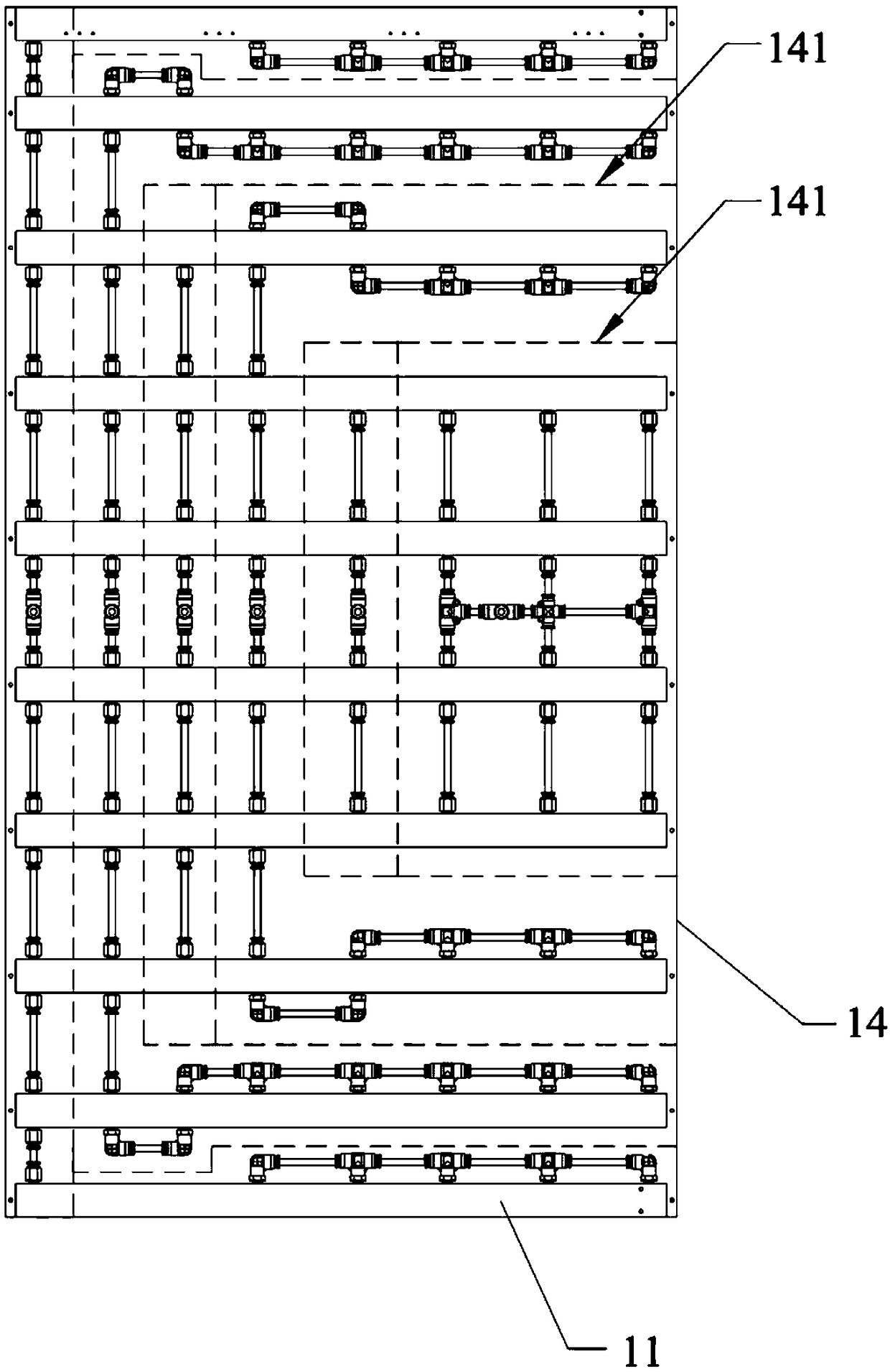
[0044] like Figure 1~5As shown, the present embodiment provides a transfer mechanism, the transfer mechanism includes a first bracket 1 and a plurality of first suction cup assemblies 2, the first bracket 1 is divided into a plurality of installation areas 141, the first suction cup assembly 2 and a plurality of installation areas 141 The areas 141 correspond one-to-one, each first suction cup assembly 2 includes a plurality of first vacuum chucks 21, the plurality of first vacuum chucks 21 are installed in the corresponding installation area 141, and the plurality of first vacuum chucks 21 They are connected by an air path, and the closing and opening of the air path can simultaneously control a plurality of first vacuum chucks 21 to suck vacuum or break the vacuum. It should be noted that the first vacuum chucks 21 of the plurality of first chuck assemblies 2 are all located in the same plane. In this embodiment, different adsorption areas can be combined by controlling th...
Embodiment 2
[0049] like Figure 6-8 As shown, this embodiment provides a transfer mechanism. On the basis of Embodiment 1, the transplant mechanism also includes a second bracket 4 and a plurality of second suction cup assemblies 3, and the second bracket 4 is installed on the first bracket 1 On the first side of the first side, a plurality of second suction cup assemblies 3 are installed on the second bracket 4 at intervals.
[0050] See Image 6 and Figure 7 The second suction cup assembly 3 includes a first driving device 31 and a second vacuum suction cup 32 connected to the output end of the first driving device 31 , driven by the first driving device 31 , the second vacuum suction cup 32 can reciprocate. In this embodiment, the driving direction of the first driving device 31 is perpendicular to the upper surface of the bakelite board 14 , and the driving stroke of the first driving device 31 can be adjusted within the range of its maximum extension length. Specifically, the sec...
Embodiment 3
[0061] like Figure 9-10 As shown, this embodiment provides a transplanting mechanism. On the basis of Embodiment 2, the transplanting mechanism in this embodiment also includes a plurality of third suction cup assemblies 5, and a plurality of third suction cup assemblies 5 are installed on the first The side of the second side of bracket 1. In this embodiment, the second side and the first side of the first bracket 1 are adjacent two sides, of course, they can also be set as opposite two sides according to actual needs. The third suction cup assembly 5 is used to absorb the PCB 300 located on the second side of the first support 1 , and prevent the PCB 300 on the second side of the first support 1 from sagging relative to the panel 100 , and also prevent the FPC 200 attached to the PCB 300 from bending.
[0062]The third suction cup assembly 5 includes a second driving device 51 and a third vacuum suction cup 52, one end of the second driving device 51 body is installed on t...
PUM
 Abstract
Description
Claims
Application Information
 - R&D
- Intellectual Property
- Life Sciences
- Materials
- Tech Scout
- Unparalleled Data Quality
- Higher Quality Content
- 60% Fewer Hallucinations
Browse by: Latest US Patents, China's latest patents, Technical Efficacy Thesaurus, Application Domain, Technology Topic, Popular Technical Reports.
© 2025 PatSnap. All rights reserved.Legal|Privacy policy|Modern Slavery Act Transparency Statement|Sitemap|About US| Contact US: help@patsnap.com