Gear box oil pump having oil unloading structure, and gear box

A gearbox and oil pump technology, applied in the field of machinery, can solve the problems of increased oil leakage, deformation of the oil pump casing and diaphragm, etc., and achieves the effect of reducing the axial force and improving the service life.

Pending Publication Date: 2019-01-01
江阴华欧德汽车动力系统研发有限公司
0 Cites 0 Cited by

AI-Extracted Technical Summary

Problems solved by technology

[0005] The present invention provides a gearbox oil pump and a gearbox with an oil unloading structure to solve the problem that in the prior art, due to the presence of hydrauli...

Method used

Further, on dividing plate 2, be provided with communicating hole 5, communicating hole 5 is positioned on dividing plate 2 and on the position corresponding to this annular groove 3, makes communicating hole 5 can be communicated with annular groove 3, simultaneously, communicates The hole 5 can also communicate with the oil suction channel of the transmission oil pump through the oil groove. Therefore, the liquid oil entering the annular groove 3 can return to the oil suction port of the transmission oil pump through the communication hole 5, so as to effectively reduce the accumulation of liquid oil in the gap between the casing 1 and the separator 2 of the transmission oil pump.
Further, the outer edge and inner edge of annular groove 3 can be all set to circular, that is, annular groove 3 is the annulus of band groove, and the center of circle of annular groove 3 coincides with the axial center of driven gear simultaneously, And the diameter of the inner edge of the annular groove 3 is greater than that of the driven gear. In this way, the distance between the annular groove 3 and the driven gear in all directions is equal, so that the oil leaked between the partition plate 2 and the housing 1 can evenly flow into the annular groove 3, and the local annular groove 3 is prevented from being subjected to excessive oil pressure. In addition, the annular groove 3 is concentric with the driven gear, which is also conducive to balancing the distribution of the center of gravity of the oil pump.
The gearbox oil pump with oil unloading structure provided by the present invention, by setting the annular groove on the surface of the oil pump housing that fits with the partition plate, als...

Abstract

The invention provides a gear box oil pump having an oil unloading structure, and a gear box. The gear box oil pump is characterized in that a shell is provided with an annular groove and an oil unloading channel, the annular groove is positioned on the outer side of an oil pump rotor, and is arranged on the surface, attached to a separation plate, of the shell, the oil unloading channel is communicated to the annular groove, the separation plate is provided with a communication hole, one end of the communication hole is communicated to the annular groove, and the other end of the communication hole is communicated to the oil suction channel of the gear box oil pump. According to the present invention, the annular groove and the oil unloading channel communicated to the annular groove arearranged on the oil pump shell, and the communication hole respectively communicated to the annular groove and the oil suction channel of the oil pump is arranged on the position, corresponding to theannular groove, of the separation plate, such that the oil liquid in the gap between the oil pump shell and the separation plate can be discharged to the oil suction port of the oil pump so as to slow down the rising speed of the oil pressure in the gap between the oil pump shell and the separation plate, effectively reduce the axial force of the oil liquid on the part in the oil pump, and improve the service life of the oil pump.

Application Domain

Technology Topic

Image

  • Gear box oil pump having oil unloading structure, and gear box
  • Gear box oil pump having oil unloading structure, and gear box
  • Gear box oil pump having oil unloading structure, and gear box

Examples

  • Experimental program(1)

Example Embodiment

[0024] Embodiment one
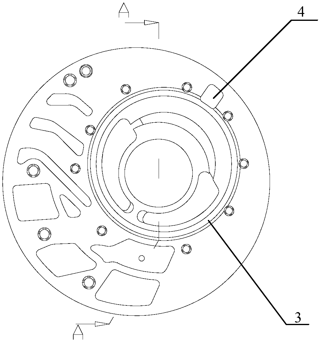
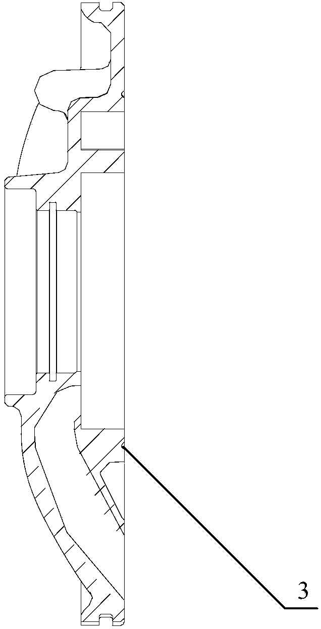
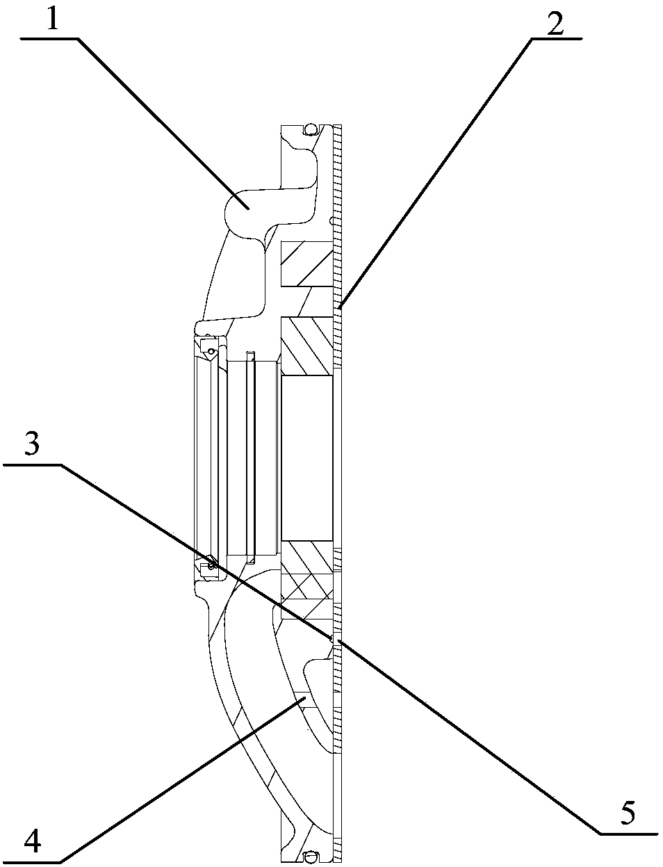
[0025] figure 1 A schematic front view of a casing of a transmission oil pump with an oil unloading structure provided in Embodiment 1 of the present invention. figure 2 for figure 1 A-A cross-sectional schematic diagram in. image 3 It is a schematic structural diagram of a transmission oil pump with an oil unloading structure provided in Embodiment 1 of the present invention. like Figure 1 to Figure 3 As shown, the gearbox oil pump with oil unloading structure provided in this embodiment includes: the casing 1 and the partition 2 of the oil pump fixedly connected, and the oil pump rotor arranged in the cavity surrounded by the casing 1 and the partition 2 (not shown in the figure), the housing 1 is provided with an annular groove 3 and an oil discharge passage 4, the annular groove 3 is located on the outside of the oil pump rotor, and the annular groove 3 is arranged on the joint between the housing 1 and the partition plate 2 On the surface; the unloading oil channel 4 communicates with the annular groove 3.
[0026] Specifically, the oil pump rotor includes a driving gear and a driven gear, the outer teeth of the driving gear mesh with the inner teeth of the driven gear, and a crescent-shaped partition is arranged between the driving gear and the driven gear, and the crescent-shaped partition separates the driving gear The working chamber between the driven gear and the driven gear is divided into an oil suction chamber and an oil pressure chamber. The oil suction chamber communicates with the oil inlet passage. When the driving gear is disengaged, the volume of the oil suction chamber gradually increases, creating a vacuum, and the oil is sucked in; the rotor continues to rotate, and the oil is brought to the side of the oil outlet passage. At this time, the active gear The gear and the driven gear just come into mesh, so that the volume of the oil pressure chamber decreases, the oil pressure increases, and the machine oil is squeezed out from the oil pressure chamber and sent out through the oil outlet channel. That is, the oil suction chamber is a low pressure area, while the oil pressure chamber is a high pressure area. At the same time, the area of ​​the crescent-shaped partition in the rotor of the oil pump is a transition area, which is used to separate the oil suction chamber and the oil pressure chamber, and the pressure in the transition area is between the oil suction chamber and the oil pressure chamber.
[0027] The annular groove 3 provided on the casing 1 is located on the bonding surface between the casing 1 and the partition plate 2, and an oil discharge passage 4 is also provided on the casing 1, and the oil discharge passage 4 communicates with the annular groove 3, so that the casing The liquid oil in the gap between the body 1 and the separator 2 first flows into the oil unloading passage 4, and then flows into the annular groove 3 through the oil unloading oil passage 4. Therefore, in order to make the liquid oil flow smoothly to the oil discharge passage 4, preferably, the oil discharge passage 4 can be arranged in the low pressure area of ​​the transmission oil pump, so that the liquid oil can smoothly enter the low pressure area from the high pressure area. Certainly, the oil discharge oil channel 4 can also be arranged in the transition area of ​​the gearbox oil pump, so that the liquid oil enters the transition area from the high pressure area.
[0028] Further, the inner edge of the annular groove 3 should be positioned at the outer side of the oil pump rotor. Meanwhile, in order to facilitate the layout of the oil discharge oil passage 4, the oil discharge oil passage 4 can be set on the outer edge of the annular groove 3, so that the oil discharge oil passage 4 and the The outer edge of the annular groove 3 communicates.
[0029] Further, a communication hole 5 is provided on the partition plate 2, and the communication hole 5 is located on the partition plate 2 at a position corresponding to the annular groove 3, so that the communication hole 5 can communicate with the annular groove 3, and at the same time, the communication hole 5 also It can communicate with the oil suction channel of the transmission oil pump through the oil groove. Therefore, the liquid oil entering the annular groove 3 can return to the oil suction port of the transmission oil pump through the communication hole 5, so as to effectively reduce the accumulation of liquid oil in the gap between the casing 1 and the separator 2 of the transmission oil pump.
[0030] Preferably, in order to increase the speed and oil volume of liquid oil entering the annular groove, and reduce the accumulation of liquid oil as soon as possible, the number of oil discharge oil passages 4 can be set to multiple, and a plurality of oil discharge oil passages 4 are distributed at intervals in the oil suction The outer side of the cavity or the transition zone, and communicates with the outer edge of the annular groove 3. Specifically, the oil unloading oil passages 4 may be arranged at equal intervals. Further, the width of the plurality of oil discharge passages 4 can be set to be greater than the width of the annular groove 3 . Specifically, the width of the annular groove 3 can be set to 2mm, and the depth of the groove is 0.8mm. The oil discharge passage 4 can be set as an oil discharge through hole with a width greater than 2mm, and then communicated with the annular groove 3 .
[0031] Further, the outer edge and the inner edge of the annular groove 3 can be set to a circle, that is, the annular groove 3 is a grooved ring, and the center of the annular groove 3 coincides with the axis of the driven gear, and the annular groove 3. The diameter of the inner edge is greater than that of the driven gear. In this way, the distance between the annular groove 3 and the driven gear in all directions is equal, so that the oil leaked between the partition plate 2 and the housing 1 can evenly flow into the annular groove 3, and the local annular groove 3 is prevented from being subjected to excessive oil pressure. In addition, the annular groove 3 is concentric with the driven gear, which is also conducive to balancing the distribution of the center of gravity of the oil pump.
[0032] The gearbox oil pump with oil unloading structure provided by the present invention is provided with an annular groove on the surface of the oil pump housing that fits with the baffle, and also has an oil unloading oil passage that communicates with the annular groove. A communication hole is provided at the position corresponding to the annular groove, which communicates with the oil suction channel of the annular groove and the oil pump respectively, so that the oil in the gap between the oil pump casing and the partition plate can be discharged to the oil suction port of the oil pump, so as to slow down the contact between the oil pump casing and the oil suction channel. The rising speed of the oil pressure in the gap of the partition plate effectively reduces the axial force of the oil in the gap of the oil pump on the parts of the oil pump, and also reduces the axial stress of the assembly bolts, which improves the service life of the oil pump.
[0033] In addition, the present invention also provides a gearbox, including the gearbox oil pump with oil unloading structure as described in the first embodiment, wherein the specific structure and functions of the gearbox oil pump with oil unloading structure have been implemented in the aforementioned A detailed description is given in Example 1, which will not be repeated here.
[0034]The gearbox provided by the present invention includes a gearbox oil pump with an oil unloading structure, an annular groove is provided on the surface of the oil pump housing that fits with the partition plate, and an oil unloading passage communicated with the annular groove is also provided. There is a communication hole on the partition plate corresponding to the annular groove, which communicates with the annular groove and the oil suction channel of the oil pump respectively, so that the oil in the gap between the oil pump casing and the partition plate can be discharged to the oil suction port of the oil pump to slow down The rising speed of the oil pressure in the gap between the oil pump shell and the partition plate effectively reduces the axial force of the oil in the gap of the oil pump on the components in the oil pump, and also reduces the axial stress of the assembly bolts, which improves the service life of the oil pump.

PUM

no PUM

Description & Claims & Application Information

We can also present the details of the Description, Claims and Application information to help users get a comprehensive understanding of the technical details of the patent, such as background art, summary of invention, brief description of drawings, description of embodiments, and other original content. On the other hand, users can also determine the specific scope of protection of the technology through the list of claims; as well as understand the changes in the life cycle of the technology with the presentation of the patent timeline. Login to view more.

Similar technology patents

Four-shunting speed reducer for crusher

PendingCN114183503AImprove rigidityReduce axial forceToothed gearingsGearing detailsLoad distributionCrusher
Owner:ZHEJIANG EVERGEAR DRIVING MACHINE

Back-up roll bearing for straightening machine

PendingCN113565870AReduce axial forceReduce frictionBall and roller bearingsBearing componentsBackup rollIndustrial engineering
Owner:辽宁德润新材科技有限公司

Water turbine

ActiveCN109139335AReliable structureReduce axial forceHydro energy generationReaction enginesEngineeringPower turbine
Owner:江西省莲花水轮机厂有限公司

Classification and recommendation of technical efficacy words

  • Extended service life
  • Reduce axial force

Vertical Woltmann water meter

InactiveCN102322901AReduce axial forceHigh sensitivityVolume/mass flow by mechanical effectsImpellerEngineering
Owner:TIANJIN JINMIAO WATER METER MFG

Impact drill

ActiveCN101204740AIncrease kinetic energyReduce axial forcePortable drilling machinesDrill bitEngineering
Owner:POSITEC POWER TOOLS (SUZHOU) CO LTD

Pump shaft axial force adaptive adjusting suspended magnetic pump

PendingCN111396322AReduce axial forceReduce frictionSpecific fluid pumpsPump componentsImpellerMorse taper
Owner:江苏威德凯泵业科技有限公司

High-efficiency rzeppa constant velocity universal joint

PendingCN112211915AReduce axial forceReduce feverYielding couplingPhysicsConstant-velocity joint
Owner:WANXIANGQIANCHAO CO LTD +1
Why Eureka
Try Eureka