Heat pump drying room dehumidification control system based on time and target, and dehumidification method

A drying room and time technology, applied in the field of drying, can solve the problems of vicious cycle and energy waste, relative humidity cannot be effectively reduced, and drying process cannot be carried out normally, etc., and achieve the effect of simple structure and easy use

Active Publication Date: 2019-01-01
HENAN BAIHENG ENERGY SAVING TECH
View PDF6 Cites 4 Cited by
  • Summary
  • Abstract
  • Description
  • Claims
  • Application Information

AI Technical Summary

Problems solved by technology

Due to the limited air temperature rise, the relative humidity drop is limited, which will cause the relative humidity in the drying room to be unable to drop effectively, so that the dehumidification process cannot be terminated, resulting in a vicious cycle and a great w

Method used


Image

  • Heat pump drying room dehumidification control system based on time and target, and dehumidification method

Examples


Embodiment Construction

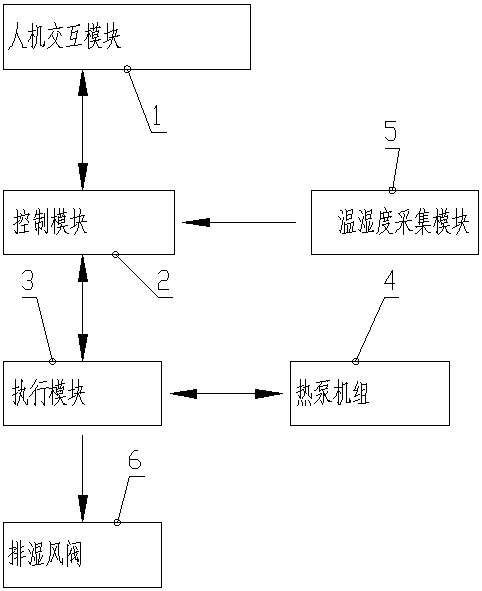
[0039] figure 1 The direction indicated by the middle arrow is the transmission direction of information.

[0040] Such as figure 1 As shown, the time-based and target-based heat pump drying room humidity control system of the present invention includes a drying room, a human-computer interaction module 1 for human-computer interaction, a control module 2, an execution module 3, a heat pump unit 4, a temperature and humidity Acquisition module 5 and humidity exhaust air valve 6; humidity exhaust air valve 6 is installed at the drying room and is used to discharge the hot and humid air in the drying room; heat pump unit 4 is used to provide heat energy for the drying room; the drying room is a conventional technology, not shown. The human-computer interaction module 1 includes a display screen and an input device. When the display screen is a touch screen, it has both the functions of a display screen and an input device. When an ordinary non-touch display screen is used, t...


PUM


Abstract

The invention discloses a heat pump drying room dehumidification control system based on time and a target. The system comprises a drying room, a human-computer interaction module used for human-computer interaction, a control module, an execution module, a heat pump unit, a temperature and humidity acquisition module and a dehumidification air valve. The control module is provided with a parameter storage inside. The invention further discloses a dehumidification method. The dehumidification method comprises the steps of firstly, carrying out drying operation according to an existing technology; secondly, carrying out air valve opening and closing cycle operation based on time on the dehumidification air valve; and thirdly, carrying out air valve opening and closing cycle operation basedon the humidity target and time on the dehumidification air valve till drying operation is finished. With the heat pump drying room dehumidification control system based on time and the target, and the dehumidification method, it can be guaranteed that effective dehumidification operation is carried out on the drying room, energy loss caused by the situation that the dehumidification air valve isopened for too long is avoided as well, it is avoided that a drying technology cannot be normally carried out because the temperature in the drying room cannot rise effectively, the purposes of energysaving and benefit increase are achieved, and the purpose of guaranteeing effective operation of the drying technology is achieved.

Description

technical field [0001] The invention relates to the technical field of drying, in particular to a method for dehumidifying a barbecue system using a heat pump as a heat source. Background technique [0002] Under the general situation of the national environmental protection policy, the baking equipment using the heat pump as the heat source has gradually become the trend of socialized heat source supply. Once the heat pump drying system is installed, the maximum amount of heat it can generate is fixed. [0003] Under harsh working conditions, such as continuous rainy weather and low ambient temperature, it is easy to dehumidify for a long time (before the humidity requirement is not met), thus accelerating the heat loss, but not dehumidifying will affect the material's performance drying quality. [0004] The existing heat pump drying system includes a drying room, a human-computer interaction module for human-computer interaction, a control module, an execution module, a...

Claims


Application Information

Patent Timeline
IPC IPC(8): F26B9/06F26B21/02F26B25/22
CPCF26B9/06F26B21/02F26B25/22
Inventor 程烨张二宾曹坤文孟祥坤杨德亮卢邦伟都洪阳
Owner HENAN BAIHENG ENERGY SAVING TECH
Why Eureka
Try Eureka