Method for testing profile accuracy of coated surface

A technology of precision testing and surface type, which is applied in the direction of measuring devices, instruments, and optical devices, etc., can solve the problems of low multi-point efficiency, inability to meet the surface accuracy, and accuracy cannot be guaranteed, so as to avoid the risk of damage and improve Test efficiency and test accuracy, reduce the effect of surface accuracy measurement error

Active Publication Date: 2019-01-01
XIAN INSTITUE OF SPACE RADIO TECH
View PDF9 Cites 14 Cited by
  • Summary
  • Abstract
  • Description
  • Claims
  • Application Information

AI Technical Summary

Problems solved by technology

[0003] The traditional surface measurement methods mainly include theodolite intersection measurement, photogrammetry, articulated arm contact measurement and three-coordinate measuring machine contact measurement. However, due to the characteristics of the surface etching coating, in order to protect the coating layer from damage, the surface cannot be Paste the measuring target with glue layer, and at the same time theodolite intersect measurement, articulated arm and three-coordinate measurement surface multi-point efficiency is low, and the accuracy cannot be guaranteed. The three-coordinate measuring machine needs special clamping tooling, but the clamping is very easy to cause paper honeycomb Distortion of the material and the datum cannot be unified
In short, the existing traditional measurement methods have been unable to meet the measurement work of the surface profile accuracy

Method used


Image

  • Method for testing profile accuracy of coated surface
  • Method for testing profile accuracy of coated surface
  • Method for testing profile accuracy of coated surface

Examples


Embodiment Construction

[0036] The present invention will be described in detail below in conjunction with the accompanying drawings and specific embodiments.

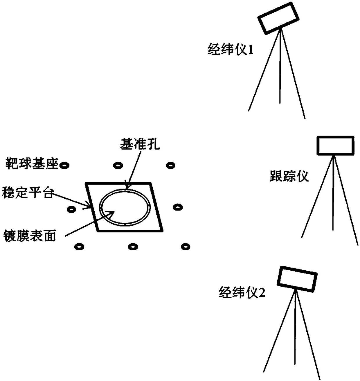
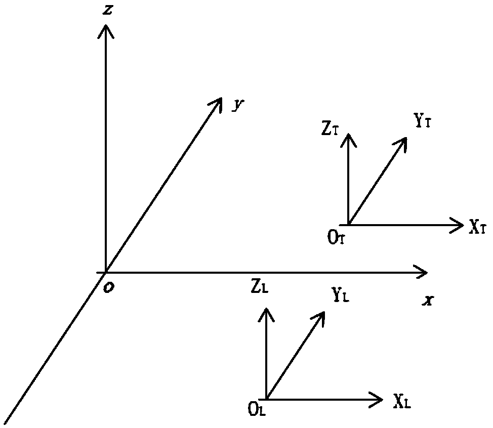
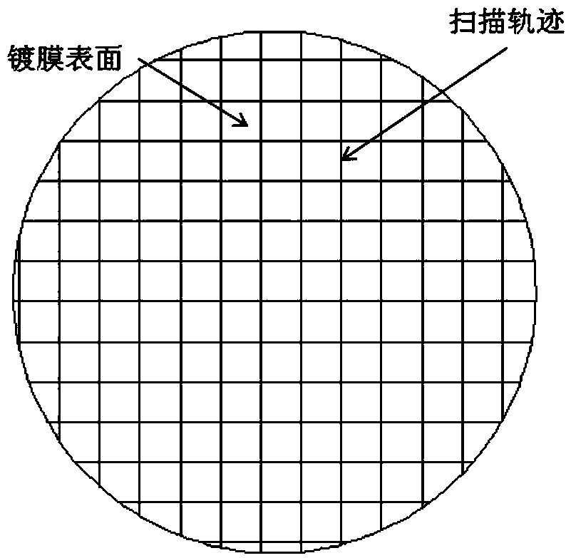
[0037] The invention provides a method for testing the accuracy of the coating surface profile. The method uses a laser tracking test system combined with a traditional double theodolite intersection measurement system to complete the spatial scanning measurement of the coating target surface profile accuracy on the basis of the conversion of the test reference. Through the target thickness compensation, the direct comparison measurement of the surface accuracy of the high-precision coating is realized, which avoids the risk of damage to the coating due to glue remaining at the pasting mark point, and at the same time greatly improves the test efficiency and accuracy.

[0038] The following is a detailed description with a specific example:

[0039] (1) Place the coated surface of the measured object on a stable platform without stress, and a...


PUM


Abstract

The invention discloses a method for testing the profile accuracy of a coated surface, comprising the following steps: measuring the coordinate values of the centers of theodolite target balls and thereference holes of a coated surface in a double-theodolite intersection measurement coordinate system; obtaining the spatial coordinate values of the centers of the theodolite target balls in a coated surface reference coordinate system by reference conversion; replacing the double-theodolite target balls with tracker target balls, and measuring the spatial coordinate values of the centers of thetracker target balls in a tracker measurement coordinate system by laser tracking measurement; using a tracker to scan and measure the trajectories and spatial coordinate values of the center pointsof the tracker target balls in the tracker measurement coordinate system by means of spatial scanning measurement; obtaining the coordinate values of the trajectory of the center point of a scanning tracker target ball in the coated surface reference coordinate system by reference conversion; and obtaining the profile accuracy of the measured coated surface according to the normal deviation between the spatial coordinate values of the points on the trajectory of the center point of the scanning tracker target ball in the reference coordinate system and the theoretical model of the coated surface in the reference coordinate system.

Description

technical field [0001] The invention relates to a method for testing the profile accuracy of a coating surface, belonging to the technical field of antenna mechanical measurement. Background technique [0002] The sub-reflector of a relay satellite S / Ka antenna has a size of 400mm. It is made of paper honeycomb material. High-precision, high-reliability test requirements are put forward. [0003] The traditional surface measurement methods mainly include theodolite intersection measurement, photogrammetry, articulated arm contact measurement and three-coordinate measuring machine contact measurement. However, due to the characteristics of the surface etching coating, in order to protect the coating layer from damage, the surface cannot be Paste the measurement target with glue layer, and at the same time theodolite intersect measurement, articulated arm and three-coordinate measurement surface multi-point efficiency is low, and the accuracy cannot be guaranteed. The three-c...

Claims


Application Information

Patent Timeline
Patent Type & Authority Applications(China)
IPC IPC(8): G01B11/24
CPCG01B11/24
Inventor 刘博学柏宏武李冬兰亚鹏李奇骏王斌程建
Owner XIAN INSTITUE OF SPACE RADIO TECH
Why Eureka
Try Eureka