A coded laser transceiver device, distance measuring device and laser radar system

A technology of laser transceiver and laser emission, which is applied to radio wave measurement systems, measurement devices, instruments, etc., can solve problems such as errors in distance measurement results, mutual interference development, etc., and achieve the effect of suppressing mutual interference

Active Publication Date: 2020-04-24
HESAI TECH CO LTD
View PDF2 Cites 27 Cited by
  • Summary
  • Abstract
  • Description
  • Claims
  • Application Information

AI Technical Summary

Problems solved by technology

[0003] However, in the same measurement range, there are multiple laser radars working at the same time, for example, when multiple laser radars are installed on a car, or when multiple vehicles equipped with laser radars are close The measurement principle of radar is based on measuring the time-of-flight of emitted laser pulses. If each laser radar cannot determine whether the received light pulses are sent by itself, then there is a certain probability that when receiving light pulses from other radars, it will also It is judged as an echo signal, which leads to an error in the ranging result
When multiple laser radars work at the same time, the problem of mutual interference between different laser radars has become one of the bottlenecks restricting its development

Method used


Image

  • A coded laser transceiver device, distance measuring device and laser radar system
  • A coded laser transceiver device, distance measuring device and laser radar system
  • A coded laser transceiver device, distance measuring device and laser radar system

Examples


Embodiment Construction

[0031] The following will clearly and completely describe the technical solutions in the embodiments of the present invention with reference to the drawings in the embodiments of the present invention. Apparently, the described embodiments are only some of the embodiments of the present invention, but not all of them. Based on the embodiments of the present invention, all other embodiments obtained by persons of ordinary skill in the art without creative efforts fall within the protection scope of the present invention.

[0032] Reference herein to "one embodiment" or "an embodiment" refers to a particular feature, structure or characteristic that can be included in at least one implementation of the present invention. In the description of the present invention, it should be understood that the orientation or positional relationship indicated by the terms "upper", "lower", "top", "bottom" etc. is based on the orientation or positional relationship shown in the drawings, and i...


PUM


Abstract

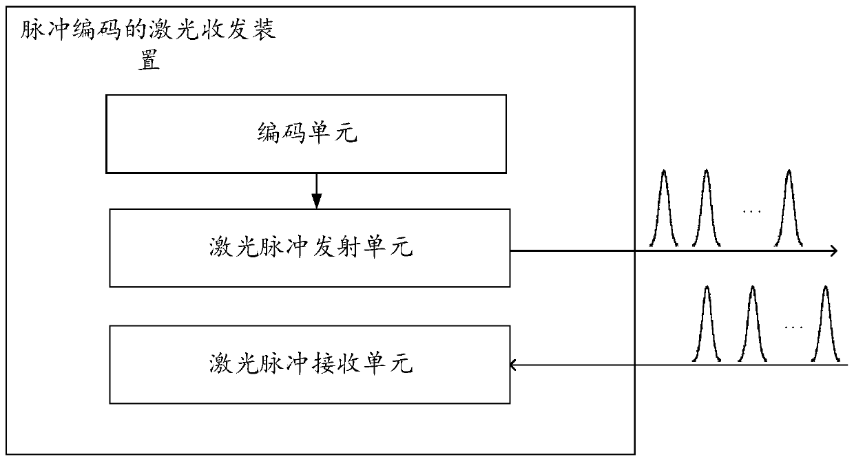
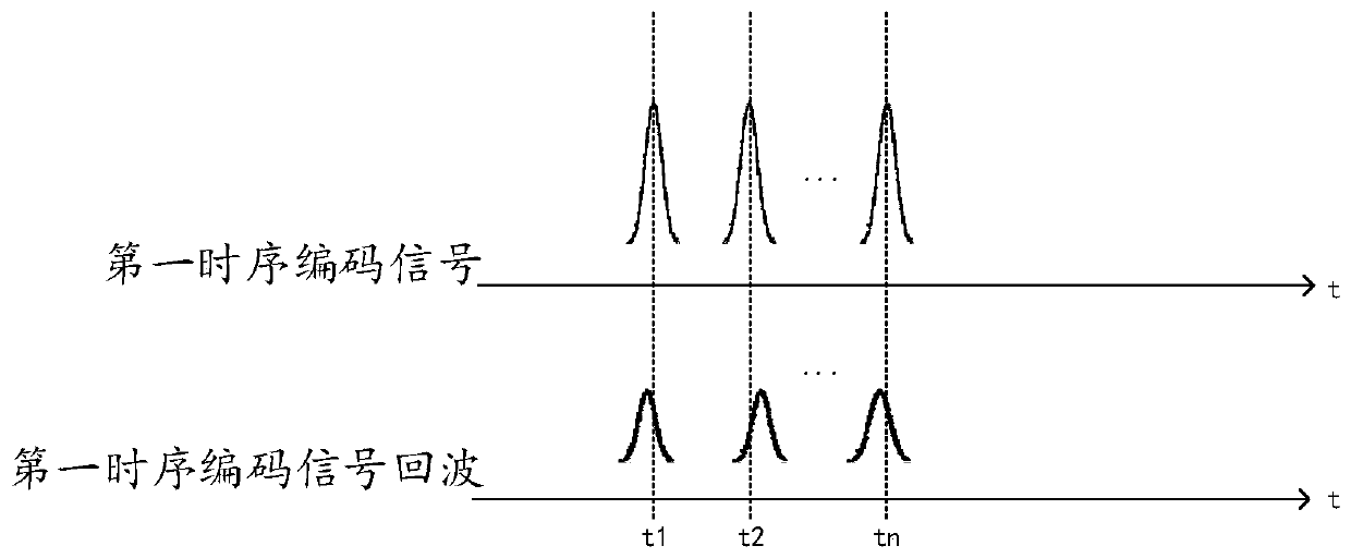
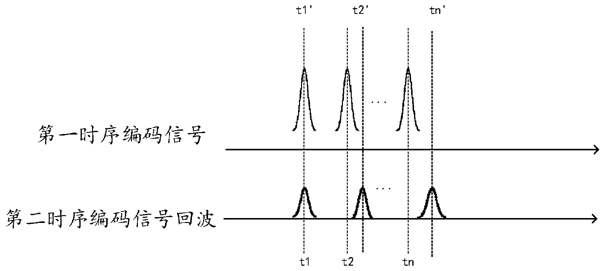
The present invention provides a pulse-coded laser transceiver, a ranging device, and a laser radar system. The device includes: a coding unit for generating a first coded signal; a laser pulse transmitting unit, based on the first coded signal, transmits a the first encoded laser pulse sequence; the laser pulse receiving unit is used to receive the echo of the laser pulse sequence, and judge whether the second encoded signal of the echo of the laser pulse sequence is the same as the first encoded signal; When an encoded signal is the same as the second encoded signal, the echo of the laser pulse sequence is used as the echo signal of the encoded laser pulse sequence.

Description

technical field [0001] The invention relates to the technical field of laser radar, in particular to a coded laser transmitting and receiving method, device and laser radar system. Background technique [0002] Long-range lidar can be used for distance measurement. It is usually based on the direct time-of-flight method, that is, by emitting a laser pulse with a narrow width but high peak power, and measuring the time of light flight back and forth between the pulsed light and the obstacle. [0003] However, in the same measurement range, there are multiple laser radars working at the same time, for example, when multiple laser radars are installed on a car, or when multiple vehicles equipped with laser radars are close The measurement principle of radar is based on measuring the time-of-flight of emitted laser pulses. If each laser radar cannot determine whether the received light pulses are sent by itself, then there is a certain probability that when receiving light puls...

Claims


Application Information

Patent Timeline
Patent Type & Authority Patents(China)
IPC IPC(8): G01S7/484G01S7/486G01S17/10G01S17/89G01S17/931
CPCG01S7/484G01S7/486G01S17/10G01S17/931G01S17/89G01S7/497G01S7/4865G01S7/4873
Inventor 朱雪洲向少卿
Owner HESAI TECH CO LTD
Why Eureka
Try Eureka