Device for generating acoustic fluid tweezers

A fluid and sound wave technology, applied in the field of microelectronic devices, can solve the problems of large eddy current size, low particle precision, and inability to meet the application requirements of similar optical tweezers operation, and achieve the effect of precise operation

Active Publication Date: 2019-01-04
TIANJIN UNIV
View PDF5 Cites 11 Cited by
  • Summary
  • Abstract
  • Description
  • Claims
  • Application Information

AI Technical Summary

Problems solved by technology

However, the size of the eddy current is large, and the precision of particle control is very low, which cannot meet the application requirements of more operations similar to optical tweezers. Currently, it is limited to online screening of particles.

Method used


Image

  • Device for generating acoustic fluid tweezers
  • Device for generating acoustic fluid tweezers
  • Device for generating acoustic fluid tweezers

Examples


Embodiment 1

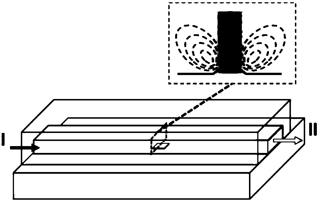
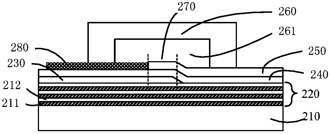
[0067] In the specific implementation process of this embodiment, the characteristic scale of the flow channel is mainly at the micron level, so the flow channel is also called a micro-channel. Microchannel is the basic unit of microfluidic system and the carrier of fluid operation. Such as figure 1 Shown is a three-dimensional schematic diagram of the device for producing acoustofluidic tweezers proposed by the present invention. Different fluid samples enter the microchannel from port I and flow out from port H. The fluid flows through the region where the bulk acoustic wave is generated (i.e. figure 1 above the boxed area shown in the microfluidic channel). figure 2 for figure 1 The center position of the bulk acoustic wave generation area in , along the cross-sectional schematic diagram perpendicular to the flow direction of the microfluid in the microchannel. Such as figure 2 As shown, the device for producing acoustic fluid tweezers includes:

[0068] The sub...

Embodiment 2

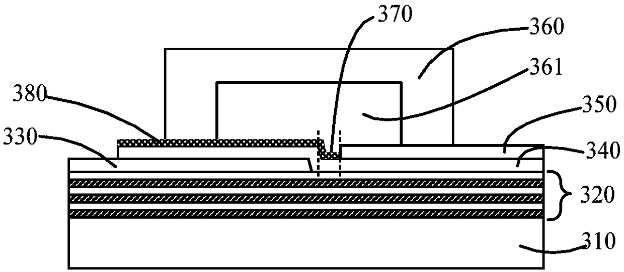
[0096] Such as image 3 As shown, the embodiment of the present application also provides a device for producing acoustic fluid tweezers, including:

[0097] Bulk acoustic wave generating components, including: a bottom electrode 330, a piezoelectric layer 340 and a top electrode 350;

[0098] Wherein, the bottom electrode 330 and the top electrode 350 are arranged on the lower and upper sides of the piezoelectric layer 340 respectively, and the bottom electrode 330 and the top electrode 350 have no overlap in the vertical direction; And a gap 370 of a specified size is formed between the portion where the piezoelectric layer 340 overlaps with the bottom electrode 330 and the top electrode 350 ;

[0099] An acoustic wave reflection part 320 arranged in contact with one side of the bulk acoustic wave generating component;

[0100] The overlapping area of ​​the bottom electrode 330, the piezoelectric layer 340, the top electrode 350 and the acoustic wave reflection part 320 co...

Embodiment 3

[0107] Such as Figure 4 As shown, the embodiment of the present application also provides a device for generating acoustofluidic tweezers. include:

[0108] Bulk acoustic wave generating components, including: a bottom electrode 440, a piezoelectric layer 430 and a top electrode 450;

[0109] Wherein, the bottom electrode 440 and the top electrode 450 are arranged on the upper side of the piezoelectric layer 430, and the bottom electrode 440 and the top electrode 450 are in the same horizontal layer; and the bottom electrode 440 and the A gap 470 is formed between the top electrodes 450;

[0110] An acoustic wave reflector 420 arranged in contact with one side of the bulk acoustic wave generating component;

[0111] The overlapping area of ​​the bottom electrode 440, the piezoelectric layer 430, the top electrode 450 and the acoustic wave reflection part 420 constitutes a bulk acoustic wave generation area;

[0112] a backing layer 410 for supporting the bulk acoustic wav...


PUM


Abstract

The embodiment of the invention discloses a device for generating acoustic fluid tweezers. The device comprises at least one bulk acoustic wave generating part, an acoustic wave reflection part, a bulk acoustic wave generating area, a bottom lining layer, at least one flow channel and a passivation layer, wherein the bulk acoustic wave generating part comprises a bottom electrode, a piezoelectriclayer and a top electrode which are arranged sequentially from bottom to top; the acoustic wave reflection part is contacted with one side of the bulk acoustic wave generating part; the superposed area of the bottom electrode, the piezoelectric layer, the top electrode and the acoustic wave reflection part form the bulk acoustic wave generating area; the bottom lining layer is used for supportingthe bulk acoustic wave generating part; a part of an area of a flow channel cavity of the flow channel covers an acoustic wave action area of the at least one bulk acoustic wave generating area; and the passivation layer covers a part which is on the piezoelectric layer and does not cover the top electrode. The acoustic fluid tweezers generated by the device can realize accurate operation on objects with molecule, nanoparticle and micrometer size.

Description

technical field [0001] The invention relates to the field of microelectronic devices, in particular to a device for producing acoustic fluid tweezers. Background technique [0002] Capturing and precisely manipulating tiny particles or even single molecules has given rise to many methods for the study of biomedical physical processes, and has had a major impact on promoting basic science and applied research in related fields. In the past few decades, various particle capture and manipulation techniques have been developed, such as optical tweezers, acoustic tweezers, magnetic tweezers, and a series of techniques based on electric field control. Among them, optical tweezers are the most widely used. The advantages of high precision and controllability in the manipulation of micro-nano particles make it an important particle manipulation tool in basic research. However, optical tweezers also have some shortcomings such as low operating efficiency, obvious temperature effect,...

Claims


Application Information

Patent Timeline
Patent Type & Authority Applications(China)
IPC IPC(8): B01L3/00
CPCB01L3/50273B01L3/502761B01L2400/0436
Inventor 段学欣崔魏巍杨洋庞慰
Owner TIANJIN UNIV
Why Eureka
Try Eureka