Machining tool for die forging rotor blade

A rotor blade and die forging technology, applied in metal processing equipment, metal processing mechanical parts, positioning devices, etc., can solve the problems of affecting blade processing accuracy, inability to achieve precise positioning, and parts out of tolerance, etc., to facilitate maintenance and management, Realize the effect of automatic integration engineering and simple structure

Inactive Publication Date: 2019-01-04
AECC AVIATION POWER CO LTD
View PDF6 Cites 4 Cited by
  • Summary
  • Abstract
  • Description
  • Claims
  • Application Information

AI Technical Summary

Problems solved by technology

However, this method has the following disadvantages: Due to the domestic tooling design and manufacturing accuracy and material heat treatment level, accurate positioning cannot be achieved, and long-term use directly affects the machining accuracy of the blade, resulting in out-of-tolerance parts

Method used


Image

  • Machining tool for die forging rotor blade

Examples


Embodiment Construction

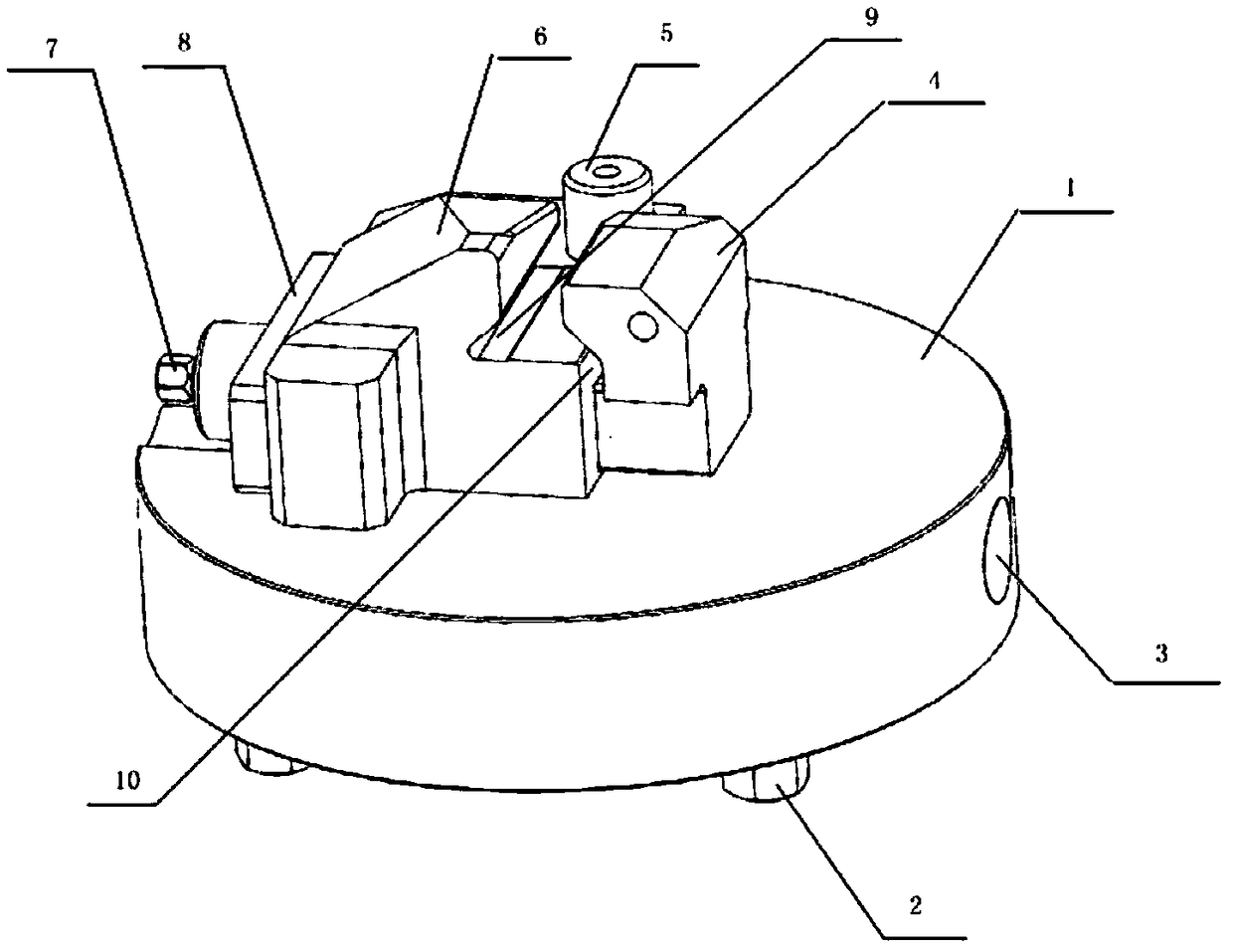
[0023] Below in conjunction with accompanying drawing, the present invention is described in further detail:

[0024] see figure 1 , a processing tool for die forging rotor blades, including a base 1, a pressure plate 4, a positioning block 6, an adjustment screw 7 and a baffle 8; one end of the positioning block 6 is connected to the pressure plate 4, the other end is connected to the baffle 8, and the positioning block 6 and the pressure plate 4. One end of the connection is provided with a positioning block groove 9; the bottom of the positioning block 6 is provided with a connecting channel that enables one end of the pressure plate 4 to enter, and this end of the pressure plate 4 can slide back and forth along the direction of the connecting channel in the connecting channel, and pass through the baffle plate 8. The adjusting screw 7 of the opened through hole is threadedly connected, and the other end of the pressure plate 4 is provided with a pressure plate groove 10, a...


PUM


Abstract

The invention discloses a machining tool for a die forging rotor blade. The machining tool comprises a base and a fixing device arranged on the upper surface of the base. The fixing device comprises apressing plate, a positioning pin, a positioning block, an adjusting screw and a baffle. The pressing plate is connected with the positioning block. The positioning block is connected with the baffle. The positioning pin is arranged on the positioning block. The adjusting screw and the pressing plate are in threaded connection. The machining tool further comprises a positioning tensioning sheet arranged on the lower surface of the base and a chip hole formed in the side edge of the base. The machining tool adopts integral structure design and is simple in structure and convenient to operate;and meanwhile, the machining rigidity of the tool is improved, and the qualified rate of parts is further increased. The base and machine tools are connected through the positioning tensioning sheet,interchangeability between the machine tools is high, the machining tool can be used on the machine tools of different brands, the positioning accuracy of a clamp and the interchangeability of the tool are improved, and management is facilitated. A chip capable of being encoded is mounted the base through the chip hole, thus automatic integration engineering is achieved advantageously, part data flow management is achieved, the serial number of each part is accurately tracked, and the machining efficiency of the parts is improved.

Description

technical field [0001] The invention belongs to the technical field of aero-engine parts processing, and relates to a die-forged rotor blade processing tool. Background technique [0002] The positioning method used in the traditional tooling design is: the tenon double-sided positioning, the bottom surface positioning and clamping method. This method fully considers the working state of the part and the tolerance of the part, and is essentially a complete positioning method based on the high precision of the tenon processing of the part. Its advantages are stable and reliable part positioning and fit parts working state. However, this method has the following shortcomings: because the domestic tooling design and manufacturing accuracy and material heat treatment level cannot achieve precise positioning, long-term use directly affects the blade machining accuracy, resulting in out of tolerance parts. SUMMARY OF THE INVENTION [0003] The purpose of the present invention ...

Claims


Application Information

Patent Timeline
Patent Type & Authority Applications(China)
IPC IPC(8): B23Q3/06
CPCB23Q3/062
Inventor 杨林延梦莹杨琼许立君张小莉马兴元魏萍庞杰
Owner AECC AVIATION POWER CO LTD
Why Eureka
Try Eureka