Multi-process integrated robot device

A robot and multi-process technology, applied in the direction of manipulators, manufacturing tools, etc., can solve the problems of small application range, reduce the transfer time, improve work efficiency, and realize the effect of automatic action

Inactive Publication Date: 2019-01-04
郑巧玲
View PDF2 Cites 0 Cited by
  • Summary
  • Abstract
  • Description
  • Claims
  • Application Information

AI Technical Summary

Problems solved by technology

[0006] The present invention aims at the above-mentioned defects in the prior art, and proposes a multi-process integrated robot device, which solves the problem that the existing multi-process integrated robot device for clamping and shipping has a small application range, and at the same time It also solves the integrated automation problem of simultaneous process processing in the process of clamping and shipping, and further solves the problem of automated material transportation

Method used


Image

  • Multi-process integrated robot device
  • Multi-process integrated robot device
  • Multi-process integrated robot device

Examples


Embodiment 1

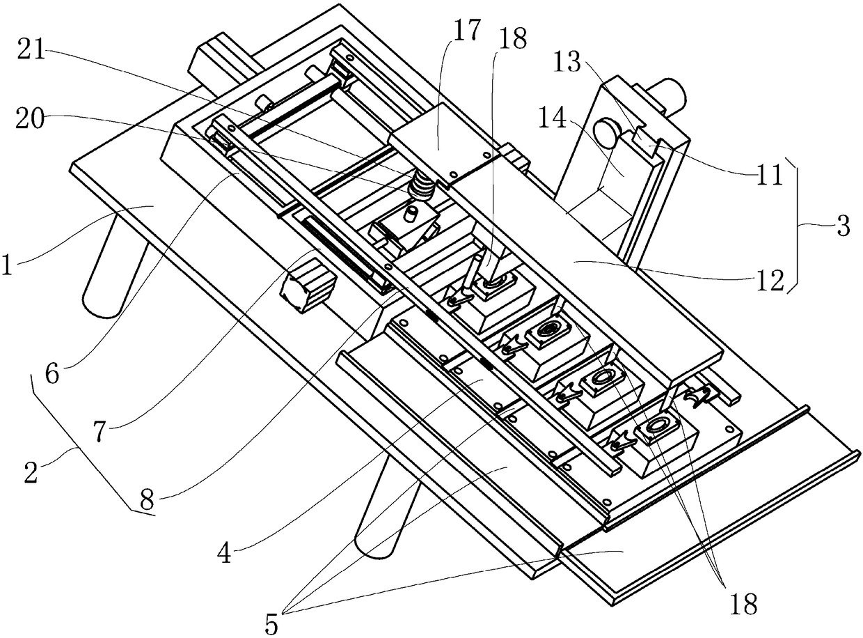
[0035] A multi-process integrated robot device in the embodiment of the present invention, such as figure 1 , figure 2 and image 3 As shown, it includes: a base 1, a slider driving part 2, a movable working part 3 and a material mold table 4, and the slider driving part 2, the movable working part 3 and the material mold table 4 are arranged on the upper part of the base 1;

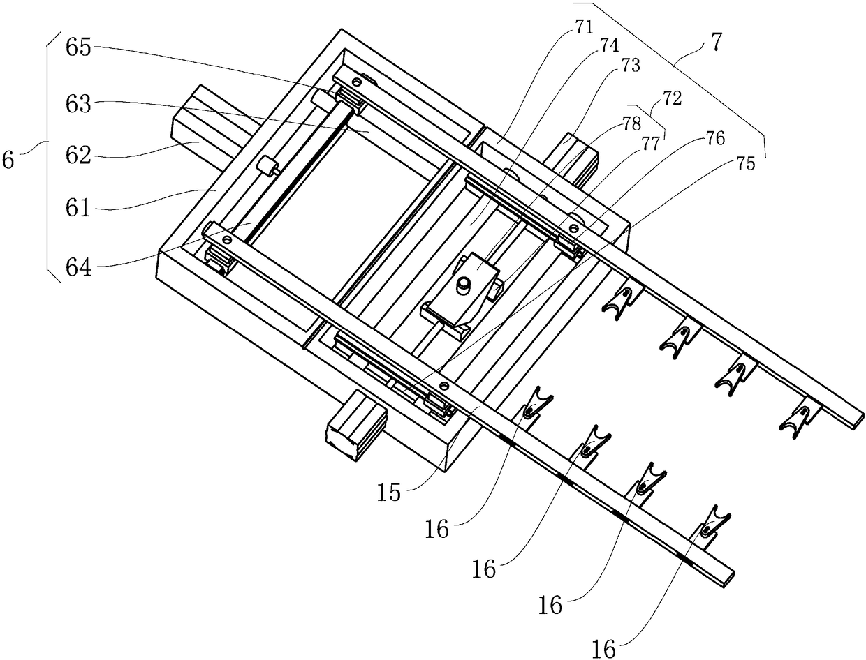
[0036] The slider drive part 2 includes a transverse drive part 6, a longitudinal drive part 7 and a material clamping device 8, the transverse drive part 6 is used to drive the material clamping device 8 to move laterally, and the longitudinal drive part 7 is used to drive the material clamping device 8 to move longitudinally. Movement: the transverse driving part 6 and the longitudinal driving part 7 are arranged side by side, and the material clamping device 8 includes two clamping arms 15 arranged in parallel on the upper part of the transverse driving part 6 and the longitudinal driving part 7. Th...

Embodiment 2

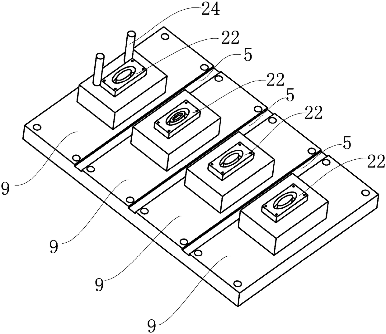
[0048] Compared with Embodiment 1, in Embodiment 2, a limit sensing device 24 is also provided on one of the mold parts 9, and the limit sensing device 24 is used to limit the lowest position of the downward movement of the die device 12. In this embodiment, The limit sensing device 24 uses a pressure sensor to realize the limit function, which has good sensitivity and reliability.

Embodiment 3

[0050] Compared with embodiment 1, on the basis of embodiment 1, embodiment 3 is provided with a pressure rod spring 21 on the top block pressure rod 20, and the pressure rod spring 21 is used for buffering, so that it will not be damaged during actual operation. The wedge-shaped top block 77 and the wedge-shaped pressing block 78 cause unnecessary damage and improve the service life of parts.


PUM


Abstract

The invention discloses a multi-process integrated robot device, and relates to the technical field of automatic devices. The multi-process integrated robot device comprises a base, a sliding block driving part, a moving working part and a material die platform, wherein the sliding block driving part comprises a transverse driving part, a longitudinal driving part and a material clamping device; the transverse driving part and the longitudinal driving part are arranged in parallel; the material clamping device comprises two clamping arms which are arranged in parallel on the transverse drivingpart and the longitudinal driving part; the transverse driving part comprises a transverse fixing frame, a transverse cylinder which is arranged at the outer side of the transverse fixing frame, a transverse guide column which is arranged in the transverse fixing frame, a longitudinal sliding rod which can slide on the transverse guide rod, and two longitudinal sliding blocks which can slide on the longitudinal sliding rod. According to the multi-process integrated robot device, the transverse driving part and the longitudinal driving part are arranged and combined; a sliding block control device is provided, so that the clamping arms can be flexibly controlled, and effective circular reciprocating movement is realized; and moreover, materials can be automatically clamped and carried.

Description

technical field [0001] The invention relates to the technical field of automation devices, in particular to a multi-process integrated robot device. Background technique [0002] In industrial production, clamping devices and robotic arms are common and very commonly used processing and clamping tools, but for smaller parts or products, there are fewer suitable clamping devices and mechanical arms, and the versatility is not strong. There are problems of troublesome parts or product transfer and more time-consuming and labor-intensive problems after adding additional multi-processes. [0003] An automatic clamping mechanism for sheets as disclosed in Chinese utility model patent CN205799293U includes a frame, and the clamping mechanism also includes a displacement assembly, a lifting drive unit and a vacuum adsorption assembly; the displacement assembly includes a setting machine The bracket on the frame, the first motor, the first pulley, and the first conveyor belt covere...

Claims


Application Information

Patent Timeline
Patent Type & Authority Applications(China)
IPC IPC(8): B25J11/00
CPCB25J11/005
Inventor 胡正义
Owner 郑巧玲
Why Eureka
Try Eureka