Automatic positioning mechanism for movable heavy-duty pallets

A technology of automatic positioning and guiding mechanism, applied in metal processing equipment, metal processing, manufacturing tools and other directions, can solve the problems of low adaptability, potential safety hazards, inaccurate positioning, etc., to achieve low cost, ingenious structure, guaranteed The effect of precise positioning

Active Publication Date: 2020-10-09
SHENYANG INST OF AUTOMATION - CHINESE ACAD OF SCI
View PDF6 Cites 0 Cited by
  • Summary
  • Abstract
  • Description
  • Claims
  • Application Information

AI Technical Summary

Problems solved by technology

[0004] In view of many deficiencies such as inaccurate positioning, low efficiency, low adaptability to automation, and potential safety hazards of traditional assembly, the purpose of the present invention is to provide an automatic positioning mechanism for movable heavy-duty pallets

Method used


Image

  • Automatic positioning mechanism for movable heavy-duty pallets
  • Automatic positioning mechanism for movable heavy-duty pallets
  • Automatic positioning mechanism for movable heavy-duty pallets

Examples


Embodiment Construction

[0025] The present invention will be described in further detail below in conjunction with the accompanying drawings.

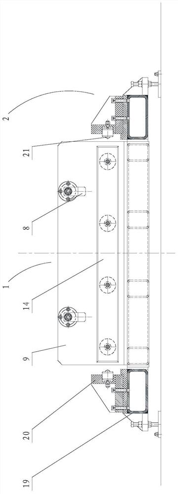
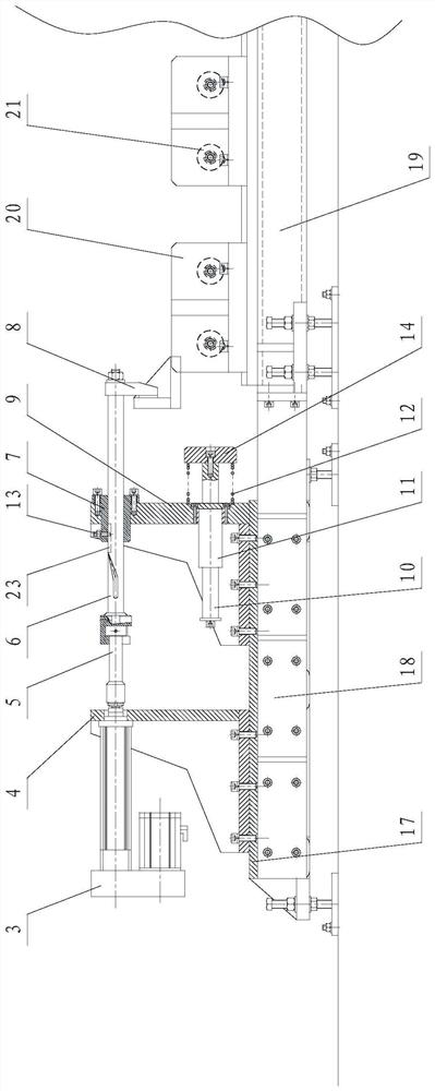
[0026] Such as Figure 1-6 As shown, the present invention includes a tensioning positioning part 1 and a base guide part 2, wherein the tensioning positioning part 1 includes an electric pull rod 3 for tension, an electric pull rod bracket 4 for tension, a connecting shaft 5, a rotating pull rod 6, and a rotating guide The sleeve 7, the tightening claw 8, the rotating rod bracket 9 and the buffer mechanism, the base guide part 2 includes a positioning base 17, a limit guide mechanism and a universal limit module.

[0027] In this embodiment, two sets of tightening positioning parts 1 with the same structure are arranged on the positioning base 17 . The tensioning electric pull rod bracket 4 and the rotating pull rod bracket 9 are respectively fixed and installed on the positioning base 17 by bolts, the tensioning electric pull rod 3 is connected to the tens...


PUM


Abstract

The invention relates to an automatic positioning mechanism for a movable heavy-load pallet. A tensioning electric pull rod support and a rotary pull rod support are respectively arranged on a positioning base, a rotary guide sleeve is arranged on the rotary pull rod support, a rotary pull rod penetrates through the rotary guide sleeve, one end of the rotary pull rod is connected with a tensioningelectric pull rod which is arranged on the tensioning electric pull rod support through a connecting shaft, the other end of the rotary pull rod is connected with a tensioning claw, and a buffer mechanism for buffering the movable heavy-load pallet is installed on the rotary pull rod support; and the two sides of the positioning base are connected with limiting guide mechanisms respectively, anda plurality of universal limiting modules are uniformly distributed on the limiting guide mechanism on each side of the positioning base in the length direction. The automatic positioning mechanism for the movable heavy-load pallet automatically adjusts and pulls the moving direction of the movable heavy-load pallet, automatically buffers and absorbs large kinetic energy cause by large impulse caused by large mass, and achieves the positioning work of a plurality of varieties of large-mass movable heavy-load pallets with strict requirements on positioning precision, thus having prominent characteristics, high positioning precision and reliable work effects.

Description

technical field [0001] The invention relates to an automatic positioning device for the transfer heavy-duty pallet where large-mass parts are located in rocket assembly, in particular to an automatic positioning mechanism for a movable heavy-duty pallet. Background technique [0002] With the increasing national strength of our country, the aerospace industry has developed rapidly. As the most important carrier for space delivery, the launch frequency of rockets for different purposes is getting higher and higher, which puts forward wider and higher requirements for its assembly. With the increasing automation of assembly, it is particularly important to ensure the efficient and high-precision positioning of the movable heavy-duty pallet during the assembly process of the rocket's large-mass parts. [0003] For the transfer and positioning of large-mass parts of rockets, the traditional method is to manually try to pull the pallets of large-mass parts to the designated asse...

Claims


Application Information

Patent Timeline
Patent Type & Authority Patents(China)
IPC IPC(8): B23P19/00
Inventor 尹健杜劲松常凯杨旭
Owner SHENYANG INST OF AUTOMATION - CHINESE ACAD OF SCI
Why Eureka
Try Eureka