A device for slotting a building wall

A wall and mounting frame technology, which is applied in the field of wall slotting devices, can solve problems such as slot size deformation, cutter head damage, and inconvenient equipment maintenance, and achieves the advantages of easy disassembly and installation, easy installation and disassembly, and improved slotting efficiency Effect

Active Publication Date: 2021-02-09
福建辰曦建筑装饰工程有限公司
View PDF3 Cites 1 Cited by
  • Summary
  • Abstract
  • Description
  • Claims
  • Application Information

AI Technical Summary

Problems solved by technology

Also there are the following deficiencies in this patent: 1, in this invention, no inclined cutter is provided, so when opening an inclined groove body, it is necessary to work simultaneously by the first screw mandrel, the second screw mandrel and the third screw mandrel, And drive the transverse cutting head or vertical cutting head to tilt and move, which will not only cause great damage to the cutting head, but also cause the size of the groove to be deformed; 2. There is no matching dust removal device, and it is still It will cause a lot of dust. Even if there is no need for manual slotting, the equipment still needs manual operation during the working process, so it will still cause workers to inhale dust; 3. Some walls are too hard, which is easy to burden the equipment, and there is no corresponding treatment method ; 4, in this invention, it is inconvenient to disassemble the equipment, therefore, it will cause inconvenient replacement of the cutter head and cumbersome maintenance of the equipment
[0004] In view of the above problems, it is necessary to provide a wall slotting device to solve the problems of excessive dust and inconvenient equipment maintenance during the slotting process

Method used


Image

  • A device for slotting a building wall
  • A device for slotting a building wall
  • A device for slotting a building wall

Examples


Embodiment Construction

[0034]The following will be combined with Figure 1 to Figure 10 The present invention is described in detail, and the technical solutions in the embodiments of the present invention are clearly and completely described. Apparently, the described embodiments are only some of the embodiments of the present invention, not all of them. Based on the embodiments of the present invention, all other embodiments obtained by persons of ordinary skill in the art without making creative efforts belong to the protection scope of the present invention.

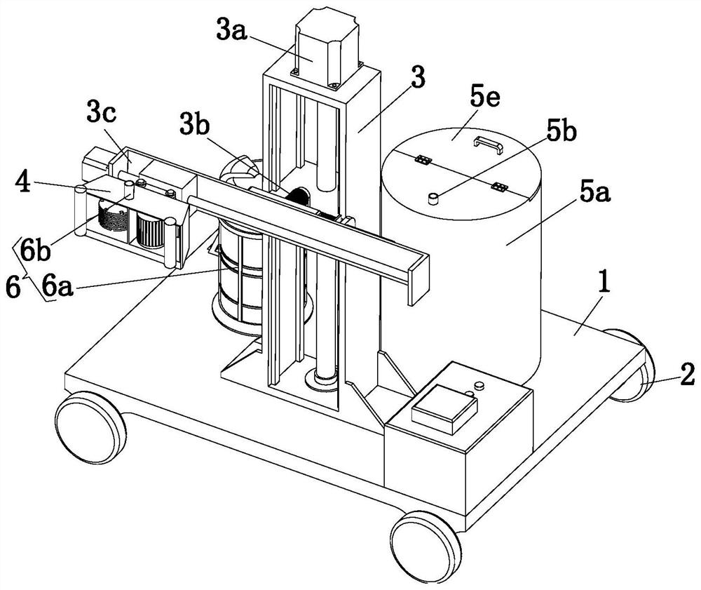
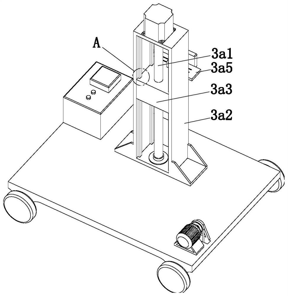
[0035] The present invention provides a wall slotting device through improvement, such as Figure 1-Figure 10 As shown, it includes a base 1, a walking mechanism 2, an adjustment mechanism 3, a slotting mechanism 4, a spraying mechanism and a dust removal mechanism 6. 6 are installed on the upper end of the base 1, the slotting mechanism 4 is fixedly connected with the adjustment mechanism 3, the adjustment mechanism 3 includes a lifting ...


PUM


Abstract

The invention relates to the technical field of building equipment, in particular to a wall grooving device. The wall grooving device comprises a base, travelling mechanisms, a regulating mechanism, agrooving mechanism, a spraying mechanism and a dust removal mechanism. The travelling mechanisms are installed at the lower end of the base, the regulating mechanism, the spraying mechanism and the dust removal mechanism are all installed on the upper end of the base, and the grooving mechanism is fixedly connected with the regulating mechanism. The regulating mechanism comprises a lifting assembly, a rotating assembly and a moving assembly. The lifting assembly is installed at the upper end of the base, the rotating assembly is installed at the upper end of the lifting assembly, and the moving assembly is fixedly connected with the rotating assembly. The grooving mechanism comprises an installation frame, a driving assembly and a grooving assembly. The installation frame is fixedly connected with the moving assembly, the driving assembly and the grooving assembly are both installed in the installation frame, and the driving assembly is connected with the grooving assembly in a transmission mode. The building wall grooving device has the beneficial effects that flying dust can be effectively reduced, grooving can be carried out at multiple angles, disassembly is convenient, and maintenance is convenient.

Description

technical field [0001] The invention relates to the technical field of construction equipment, in particular to a wall slotting device. Background technique [0002] When decorating the interior, the water and electricity pipes must be arranged first. The water and electricity pipes are generally arranged on the bottom surface or in the wall. The grooving machine etc. slowly grooving bit by bit, and its grooving speed is slow, which may easily cause the trend of the trough body to tilt, and a large amount of dust will be generated during the grooving process, which will cause damage to the worker's body. [0003] Chinese Patent No. CN107030895B discloses a wall automatic slotting device, the first bracket is fixed to the second motor base, the first lead screw is fixed on the first motor, and the second lead screw base is installed On the first lead screw nut, the camera base is installed on the lower part of the first support, the second motor base is fixed to the first su...

Claims


Application Information

Patent Timeline
Patent Type & Authority Patents(China)
IPC IPC(8): B28D1/22B28D7/00B28D7/02
CPCB28D1/22B28D7/00B28D7/005B28D7/02
Inventor 高月民袁福德李万青
Owner 福建辰曦建筑装饰工程有限公司
Why Eureka
Try Eureka