
A parallel motion vehicle deceleration system

A deceleration system and vehicle technology, applied in the direction of pneumatic brakes, railway car body parts, liquid dynamic brakes, etc., can solve the failure of brake rail surface and wheel wear, the unsatisfactory braking effect of hump reducers on heavy vehicles, and the braking The rail surface and the side of the wheel cannot be completely parallel to achieve the effect of prolonging the service life, adjustable braking force and fast response speed

Active Publication Date: 2020-01-14
XIAN UNIV OF TECH
View PDF8 Cites 0 Cited by
  • Summary
  • Abstract
  • Description
  • Claims
  • Application Information

AI Technical Summary

Problems solved by technology

[0003] The purpose of the present invention is to provide a translational vehicle deceleration system, which solves the problem in the prior art that when the hump reducer is clamped on one side, the brake rail surface cannot be completely parallel to the side of the wheel. The problem of severe wear and failure of the wheel and the unsatisfactory braking effect of the hump reducer on heavy vehicles

Method used


Image

  • A parallel motion vehicle deceleration system
  • A parallel motion vehicle deceleration system
  • A parallel motion vehicle deceleration system

Examples


Embodiment Construction

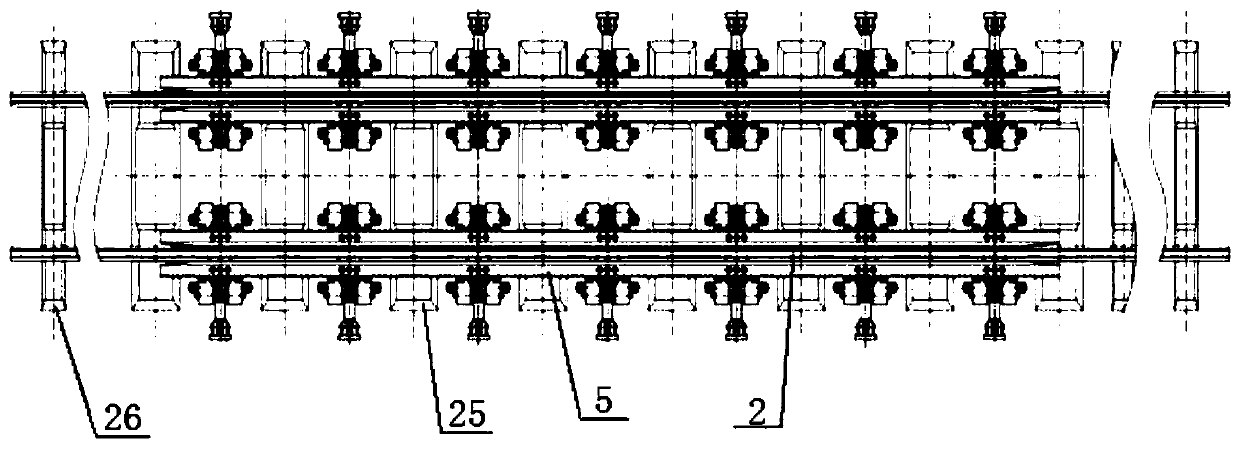
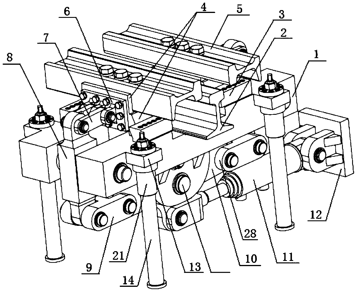
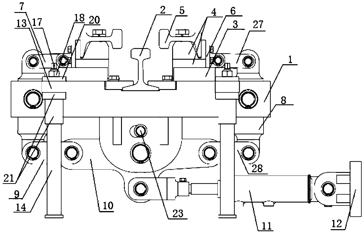
[0027] The present invention will be described in detail below in conjunction with the accompanying drawings and specific embodiments.

[0028] A deceleration system for a translational vehicle of the present invention comprises a brake mechanism, an auxiliary supporting mechanism supporting the brake mechanism is arranged under the brake mechanism; a hydraulic mechanism is arranged on one side below the brake mechanism; The mechanism is connected and drives the braking mechanism;

[0029] The braking mechanism includes a T-joist 1, a basic rail 2 is fixed in the middle of the upper surface of the T-joist 1, and the basic rail 2 is perpendicular to the beam of the T-joist 1; both ends of the upper surface of the T-joist 1 are provided with guide rail 3, and the two guide rails 3 are all parallel to the beam of the T-shaped joist 1; the two guide rails 3 are equipped with brake rail seats 4 that can move along them, and the two brake rail seats 4 are fixed with The moving rail...


PUM


Abstract

The invention discloses a translational vehicle deceleration system, comprising a braking mechanism, an auxiliary support mechanism supporting the braking mechanism is arranged below the braking mechanism; a hydraulic mechanism is arranged on the lower side of the braking mechanism; the hydraulic mechanism is connected with the braking mechanism through a transmission mechanism and drives the braking mechanism. When the wheel is braked, the surface contact between the brake rail and the wheel is formed, the wear of the brake rail and the wheel is reduced, and the service life of the brake railand the wheel is prolonged; the transmission mechanism has the effect of boosting force. By adjusting the cylinder pressure of the hydraulic cylinder, the vehicle with different weights can be controlled hierarchically, and the effective braking of the counterweight vehicle can be satisfied while the light vehicle is not extruded.

Description

technical field [0001] The invention belongs to the technical field of speed regulating equipment for railway shunting operations, and in particular relates to a deceleration system for translational vehicles. Background technique [0002] At present, the clamping action of the brake rail in the clamping type double-sided braking vehicle reducer brake device used in the hump marshalling station in my country is completed by the rotation around the central axis, and the rotation angle changes randomly during braking. The brake rail surface and the side of the wheel cannot be completely parallel, and the two planes form a line contact, resulting in unsatisfactory braking effect and serious wear of the wheel and brake rail; while the existing translational non-gravity graded brake reducer has braking force Too small, the braking effect on heavy vehicles is not ideal. Contents of the invention [0003] The purpose of the present invention is to provide a translational vehicle d...

Claims


Application Information

Patent Timeline
Patent Type & Authority Patents(China)
IPC IPC(8): B61H11/06
CPCB61H11/06
Inventor 刘宏昭张嘉华郝贵军芦恒张磊
Owner XIAN UNIV OF TECH
Learn More