a forehearth structure

A technology of material channel and distribution flow channel, which is applied in the field of processing equipment of inorganic non-metallic materials, can solve problems affecting fiber quality and yield, affecting equipment production efficiency, separate maintenance of bushing plate, etc., to improve production efficiency and ensure quality Uniformity, the effect of improving uniformity

Active Publication Date: 2020-09-22
NANJING FIBERGLASS RES & DESIGN INST CO LTD
View PDF9 Cites 0 Cited by
  • Summary
  • Abstract
  • Description
  • Claims
  • Application Information

AI Technical Summary

Problems solved by technology

During the flow process of the melt, as the melt is ejected from the bushing, along the flow direction of the melt, the flow rate of the melt decreases continuously, and its temperature also decreases continuously, resulting in that the temperature of the melt in the melt channel is not stable. Uniformity, which affects the quality and yield of fibers
At the same time, when there is a problem with one of the bushing boards, because the bushing board cannot be overhauled separately, the production can only be stopped for further repairs, which affects the production efficiency of the equipment

Method used


Image

  • a forehearth structure
  • a forehearth structure
  • a forehearth structure

Examples


Embodiment 1

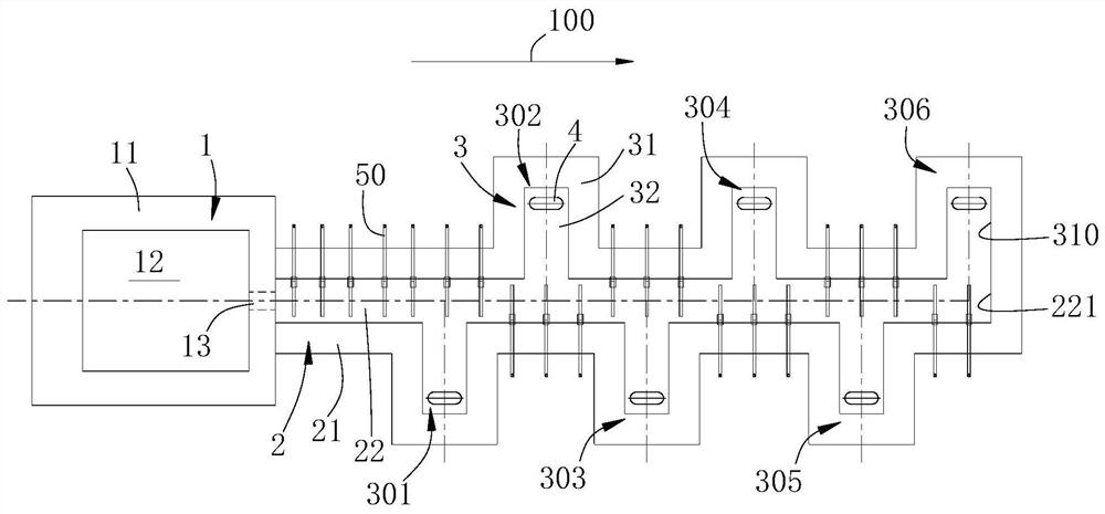
[0020] refer to figure 1 , a feedway structure, which includes a liquid flow distribution area 2 extending along a first direction 100 in a length direction, and the liquid flow distribution area 2 includes a main casing 21 and a distribution channel 22 disposed in the main casing 21; Both sides of the liquid flow distribution area 2 in the width direction are provided with ear pools 3, the ear pools 3 include a pool body 31 and a liquid flow chamber 32 arranged in the pool body 31, the liquid flow chamber 32 communicates with the distribution channel 22, and The bottom of the ear pool 3 is provided with a drain plate 4 communicating with the liquid flow cavity 32 .

[0021] Along the first direction, the ear cisterns 3 located on both sides of the width direction of the liquid flow distribution area are arranged alternately. In this embodiment, six ear pools are provided, two of which are arranged on both sides of the width direction of the liquid flow distribution area 2, a...

Embodiment 2

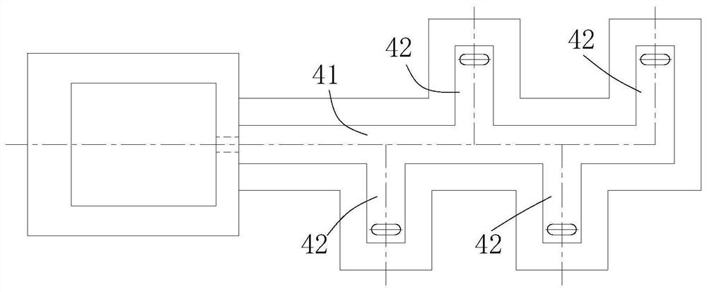
[0030] This embodiment is an improvement on the basis of Embodiment 1. The difference between this embodiment and Embodiment 1 is only the number of ear pools. Please refer to figure 2 , in this embodiment, two ear pools 42 are provided on both sides of the liquid flow distribution area 41, and the ear pools 42 on one side are spaced apart from the ear pools 42 on the other side. figure 2 In , to simplify the drawing, the heater is not shown.

Embodiment 3

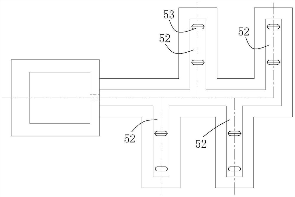
[0032] This embodiment is an improvement on the basis of embodiment 2. The difference between this embodiment and embodiment 1 is the difference in the number of bushings. Please refer to image 3 , in this embodiment, two drain plates 53 are provided in each ear pool 52 . It can be understood that, according to different production scales, the number of floors in each ear pool can be increased, for example, 3, 5 or more. image 3 In , to simplify the drawing, the heater is not shown.


PUM


Abstract

The invention discloses a material channel structure. The material channel structure comprises a liquid flow distribution area whose length direction extends along a first direction and is characterized in that liquid flow distribution area comprises a main shell and a distribution channel arranged in the main shell; at least one side of the width direction of the liquid flow distribution area isprovided with an auriculate bath, each auriculate bath comprises an auriculate bath body and a liquid flow cavity communicated with the distribution channel, and the bottom of the auriculate bath is provided with a drain plate communicated with the liquid flow cavity. The material channel structure has the advantages that molten basalt is distributed by the liquid flow distribution area to enter each auriculate bath, and the liquid flow distribution area is mainly used for distributing the molten basalt; the drain plates are not arranged in the areas of the auriculate baths, so that the lengthof the liquid flow distribution area can be reduced greatly, and the temperature change of the molten basalt in the liquid flow distribution area is reduced; due to the fact that the molten basalt synchronously enters the auriculate baths, the uniformity of the molten basalt in each auriculate bath can be increased effectively, and the quality uniformity of produced basalt fibers is guaranteed.

Description

technical field [0001] The invention relates to a production facility of basalt fiber and belongs to the field of processing equipment for inorganic non-metallic materials. Background technique [0002] Basalt is a refractory material with high melt blackness, poor heat permeability, and easy crystallization. The existing basalt continuous fiber production equipment is generally equipped with a linear melt channel. There are multiple bushings in the length direction, and with the flow of the melt, the melt is ejected from the bushings to form fibers. During the flow process of the melt, as the melt is ejected from the bushing plate, along the flow direction of the melt, the flow rate of the melt decreases continuously, and its temperature also decreases continuously, resulting in that the temperature of the melt in the melt channel is not stable. Uniformity affects the quality and yield of fibers. At the same time, when one of the bushings had a problem, because the bushin...

Claims


Application Information

Patent Timeline
Patent Type & Authority Patents(China)
IPC IPC(8): C03B7/02
CPCC03B7/02
Inventor 于守富李卫军谭良
Owner NANJING FIBERGLASS RES & DESIGN INST CO LTD
Why Eureka
Try Eureka